Let's Design and Build a (mostly) Digital Theremin!

Posted: 11/7/2020 5:51:39 PM
dewster

From: Northern NJ, USA

Joined: 2/17/2012

"Working with my D-Lev has upended what I thought I understood about the effects of bulk capacitance from nearby metal swamping out the variable capacitance presented by the player.  Even though there is nothing mystical going on it's pleasantly surprising behavior when compared to how problematic the environment can be for analog theremins."

"I've been clipping shunt capacitances onto the pitch element that would shut down my Etherwave or Subscope, yet the D-Lev plays just fine after running ACAL and sometimes adjusting linearity or other parameters.  - pitts8rh

Analog Theremins with EQ coils have a double resonance, so their tuning can be disrupted by variations in the environmental capacitance.  This is a huge reason to avoid EQ coils in both analog and digital instruments (unless you have an easily adjustable C trimmer right at the antenna, and even then no thanks).

"A while back I described how there seemed to be an interaction barrier somewhere within the body of my D-Lev Pro, roughly aligned with the center of my vertically-oriented enclosure.  To the pitch side of this barrier there is almost no influence on volume, and more importantly the volume hand has no effect on pitch until you move past this wall.  With my analog theremins I can always hear some volume influence on pitch (mostly at low pitches of course), but the D-Lev seems much more non-linear as you move your volume hand closer to the pitch side."

"Just goofing around with this one morning I brought my two hands closer together on either side of this barrier or wall of separation as I was playing.  It was ridiculous.  I had my two hands maybe 8-10 inches center to center and it played just fine with very little cross controlling."

What you describe may simply be the bulk C of your body changing?  Hands very near antennas tend to give the entire body a lower resistance to ground (terminate more C field lines) and so could lead to axis interaction - perhaps your D-Lev volume axis is adjusted so that your volume hand is playing somewhat farther away than it does for your analog Theremins?

Posted: 11/7/2020 6:26:13 PM
tinkeringdude

From: Germany

Joined: 8/30/2014

If the D-Lev is significantly less finicky with the pitch field adjustment than many or most well known, most widely spread Theremins,

then that should be one of the first, most present things on the damn marketing sheet or whatever that may be called.

"Do you want a really tunable instrument?"

Do you want a real computer and not just a toy? Buy the VIC20.
Ok, maybe that's laying it on a bit thick. note to self - stop watching retro videos

Posted: 11/7/2020 10:02:19 PM
dewster

From: Northern NJ, USA

Joined: 2/17/2012

"If the D-Lev is significantly less finicky with the pitch field adjustment than many or most well known, most widely spread Theremins, then that should be one of the first, most present things on the damn marketing sheet or whatever that may be called."  - tinkeringdude

It's second on the features list: https://d-lev.com/

The D-Lev axes are necessarily somewhat more involved to set up than an analog Theremin, but it's largely a set-and-forget kind of thing.  I haven't messed with the axis knobs in months, and I only semi-seriously mess with them when firing up a brand new prototype.

Posted: 11/8/2020 3:04:14 PM
dewster

From: Northern NJ, USA

Joined: 2/17/2012

Meow*

Following up on the discussion here, a minor eye-opener for me while researching the utility of various waveforms was this: there are very few fixed waveforms that don't sound unnatural if you significantly change the pitch.  No harmonics sounds natural.  All harmonics sounds natural.  Odd harmonics sounds natural.  A mix of all those sounds natural.  That's about it.  Just about everything else (that I've encountered) meows / sounds like a vowel change locked to pitch.

Most of us have likely experienced a ROMpler keyboard or sample set playing outside of it's captured / natural range.  Stretching these notes 1/2 an octave (or less) in pitch while not changing the waveform also stretches the resonances, and realism goes out the window.

If you really want meowing (say as a special effect or something) you can use a pitch tracking filter(s) to get a similar sound.  But most of the time when doing natural sounds with subtractive / modal synthesis you'll be doing your best to avoid it.  This is why I'm not very interested in wavetable "draw the waveform" type synthesis - I suppose it can be a lot of noodly fun, but it has limited utility, and it pulls in an additional variable - absolute phase - which is inaudible.  And it meows if you aren't dialing in bog standard waves or somehow morphing tables with pitch (at which point the mixed absolute phases in those tables will rear their ugly heads).

(*Thanks to Roger for introducing this term!  So descriptive...)

[EDIT] Some useful meowing is the Hammond organ sound, but it is seriously bolstered by polyphony, key click, attack, distortion, and rotary speaker.  Beyond that, much of its sonic allure may be due to its strangeness.

[EDIT2] I find it rather strangely opportune that the standard analog synth "meat and potatoes" waveforms consist of none / all / odd harmonics (sine, ramp/pulse, square/triangle).

Posted: 11/11/2020 12:57:03 PM
dewster

From: Northern NJ, USA

Joined: 2/17/2012

Things That Go Bump In The Night

Over the last few days of mad printing (almost through my whole new reel of white PETG!) the feed axis of my Ender started significantly popping during infill - the stepper motor was running out of torque which was allowing the filament to spring back a bit, making the infill holier than normal (and not in the divine sense).  Then it started popping during the outer faces and walls too, somewhat degrading the appearance and I imagine the integrity as well, so something had to be done. 

After watching a couple of YouTube videos, I heated up the nozzle via the control menu, removed the PETG filament, unscrewed the fan box and rubber boot, unscrewed the nozzle, and pushed the tube through.  The tube had a few mm of plastic in it that I couldn't remove, so I cut the plugged end of the tube off as square as I could.  The nozzle was full of plastic that I couldn't do much about without heating it up somehow so I left it in there.  Then I reassembled everything and it worked OK for a print or two but then started popping again.

Fed up, I spent several hours on Amazon looking at direct drive kits.  One in particular looks pretty sweet as it adds a fourth guide wheel to the X-axis, but it's made for the Ender 5, which has its X-axis drive belt rotated 90 degrees.  The others look OK but seem like they would make the carriage weight distribution fairly lopsided.

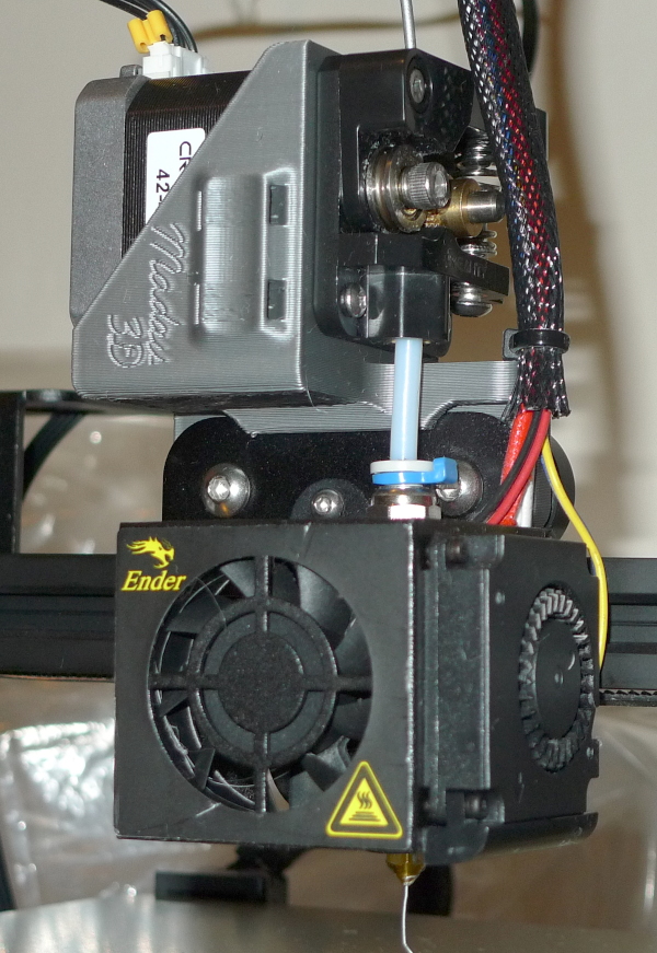
Fed up again, I went to thingiverse and found the Ender 3 Direct Drivinator, downloaded it, printed it with space gray PETG, 5 walls all around and 50% infill.  This was my first experience with break-away supports, and they worked amazingly well for supporting the underhangs.  As usual, I did a 1/2 size print first, which helped me fine-tune the final print & supports (I printed it in the orientation shown in my photo below).

Installation was pretty easy, the guide wheel bushings are pressed into the holes to basically secure it in X and Z, and a slot which accepts the carriage plate secures it in Y.  Then the extruder motor is relocated from the Z gantry to the X carriage, dramatically lowering the distance between filament feed and the hot end.  The distance is so short I decided to forego the use of the tube clamp on the feed side, and that seems to be working fine so far.  The feed drive wiring is pretty simple too, you just strip the 4 wire group off of the Z axis motor drive and thread it through the now empty extruder stepper motor hole.  I'll probably buy a new wiring harness at some point just to make this prettier and more secure (there is a convenient dual cable tie point printed into the side):

After that it was a simple matter to remove one top rail reel screw and rotate the reel of plastic filament 90 degrees, and large zip-tie next to it now loosely holds the hot end wiring harness up there too.

I'm doing test prints now.  No popping yet, and the retraction can be dramatically reduced with very little spider webbing compared to before.  It's like a different machine!  If you have an Ender 3 I highly recommend this mod, you can print it and try it in an afternoon and just back it out if for some reason you don't like it.  The only issue I've found with it is the extruder tension spring is rather obscured, but I've never encountered a need to adjust it.

Posted: 11/11/2020 2:09:31 PM
pitts8rh

From: Minnesota USA

Joined: 11/27/2015

That looks like an easy enough solution.  The path distance from extruder to hotend isn't much longer than either the Prusa or Hemera extruders, and installation-wise this is a lot easier with no loss of build volume and no firmware changes.  There should be no need for any coupler on the top end of the Bowden tube as long as it doesn't have a gap.  In fact I wouldn't be surprised if the lower coupler is now somewhat redundant. You should be able to run this with around 1.0mm of retraction, plus or minus a minor tweak. Plus you could now print TPU!

If because of the top-heaviness you run into instability or hysteresis in the x-axis that forces you to have more tire pressure than you would like, you can sometimes widen the top "wheelbase" a little if your printer allows it.  My CR10S-Pro had some extra room on the right side, so I extended the right wheel out and moved the lower center wheel half that extra distance to the right as well to keep it centered.  Having high roller pressure isn't necessarily a problem for the motors but you can develop flats if left in one position for a while.

If the machine is hammering too much because of the added mass you can reduce your X-axis acceleration a little, but watch for corner bulging on prints if you go too far.

Extension cables for the stepper are cheap from Amazon if you need one.

Nice job though,  And the PETG adapter that you printed looks about as clean as they get. BTW, is that "Madass 3D"?

Posted: 11/11/2020 2:27:32 PM
dewster

From: Northern NJ, USA

Joined: 2/17/2012

"Having high roller pressure isn't necessarily a problem for the motors but you can develop flats if left in one position for a while."  - pitts8rh

How do you know about my flats from sitting in front of the PC all day long?

"Nice job though,  And the PETG adapter that you printed looks about as clean as they get."

Thanks!  It's printed with "coarse" z stepping, which I didn't really intend to do, but it turned out fine.

"BTW, is that "Madass 3D"?"

It's "Madau 3D" but if it were "Madass 3D" I would have understood that too (it's a rather unforgiving hobby).

Posted: 11/11/2020 7:15:20 PM
dewster

From: Northern NJ, USA

Joined: 2/17/2012

Little Boxes On The Desktop, Little Boxes Made Of PETG

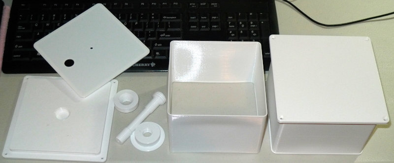
Here's two of my latest plate antenna & AFE boxes in white PETG:

After the separation fiasco I decided to again print the sides separately.  Here they're 135mm x 135mm x 100mm high, and small ribs at inside top and bottom are gripped by grooves in the front plate and back cover, which make for a tight snap fit.  The plate thread is now a female M24 x 3, which I believe is a stronger and more versatile option than a protruding plastic stud, and the back of the faceplate is reinforced with three extra solid layers at the bottom of the thread (making a total of six layers there).  The center post goes from that down to a M16 x 2 both at bottom and top for the ID coil guides that thread onto it, so at most a 16mm cutout will be required at the center of the conducting foil.  The end of the post has a 3mm hole to optionally accept a self-tapping screw to hold the back on (or I might just tape it).  Being essentially non-structural, the sides and back are printed quite thin, and you can see some bowing of the sides here that happened when I removed them from the warm printing enclosure.  The sides are entirely usable, but I plan to implement some sort of vertical corrugation to combat this.  The back is ruler flat because it was printed directly on the Ender table.

I printed the front plate with 3 layers everywhere, 25% cubic infill.  The threaded "hardware" was printed with 5 layers everywhere and with a bit more infill, as they are more structural.  It's really nice to be able to giveth and taketh away plastic as required.  And for some reason threads are a total blast to print, a fantastic enabling technology which adapts quite well to 3D printing.

Posted: 11/12/2020 4:46:37 PM
dewster

From: Northern NJ, USA

Joined: 2/17/2012

Chain Chain Chain

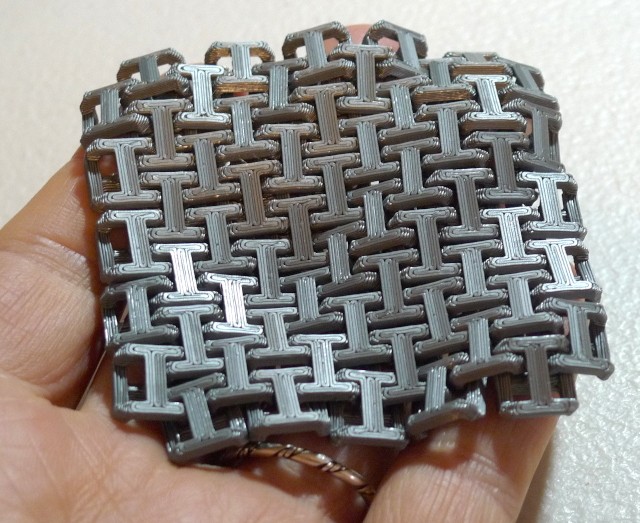
Got a chain mail pattern off thingiverse, scaled it 75%, printed in space gray PETG with coarse Z stepping & 2mm retraction:

Whole lotta retraction going on, zero spider webbing.  I know I said this, but it's like a totally different machine with the direct drive extruder.

Posted: 11/15/2020 2:48:37 PM
dewster

From: Northern NJ, USA

Joined: 2/17/2012

Lincoln Memorials

When printing super thin vertical stuff, perhaps paradoxically, any extra thickness anywhere tends to destabilize the entire structure.  I should probably go with a larger nozzle, but my desire is to print the antenna plate side walls with two passes of a 0.4mm diameter nozzle (for a total wall thickness of 0.8mm) and coarse 0.28mm Z stepping.  PLA plastic is too stiff / brittle to go this thin, but it seems doable with PETG which is much more flexible.  The center post can mostly support the back, so the sides are barely structural.  Their job is to support the aluminum foil and AFEs and keep out drafts, and they don't have to be pretty because they'll be hidden inside the larger enclosure.

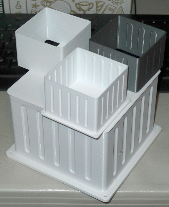
Above are three half size prints and a final (?) full size print.  The print at the upper left is where I started, where the only reinforcement is a copy of the upper / lower ridge at mid-height.  When I made this ridge larger all hell broke loose in the warping department - it was made clear to me that extra thickness was a total no-no, and that vertical stiffening was the order of the day.  The print at the upper right is my first attempt at ~constant wall thickness vertical corrugations constructed from tapered cylinder geometries covered in an SCAD "hull".  The center print ups the corrugation count from three to five, and doubles the depth.  For the full size print on the bottom I increased width of the corrugations to be the same as the corner radius. 

There's a large "snot ball" that you can see embedded in this print, it happens every time and I'm not sure why, but it isn't important.  It seems turning the cooling fan off helps warping, and sticking a plastic bag over the entire printer is a big key to thin walled printing.  There is still a bit of warpage at the top, but it's minimal enough to easily live with.  I turned off retraction, though with two wall layers there is very little retraction going on anyway.  This is a 5 hour print that consumes a scant 20m of filament.

[EDIT] I think the snot ball was caused by a leaking slightly loose nozzle.

You must be logged in to post a reply. Please log in or register for a new account.