Let's Design and Build a (mostly) Digital Theremin!

Posted: 2/3/2021 11:45:27 AM
dewster

From: Northern NJ, USA

Joined: 2/17/2012

"I've also noticed that you can tolerate much closer knob spacing in vertical columns if instead of grabbing them with your thumb and index finger tip you sort of roll them between your thumb and the side of your index finger."  - pitts8rh

Thanks!  That's exactly what I was trying to describe.  Tight vertical knob spacing needs a certain minor technique, but once you figure it out it's not a big deal.  It does require you to hold your entire hand in a certain way, which feels more awkward for me the farther to the left the knobs are, mainly due to the extended wrist angle.

"I think what you have done on your panel above is fine, and I may tighten up the encoder spacing on the new board from its current 1" to a little less."

Just for the record, these are spaced 20.32mm vertically and 40.64mm horizontally (center-to-center) on my latest panel above.

Posted: 2/5/2021 10:44:34 PM
dewster

From: Northern NJ, USA

Joined: 2/17/2012

Towards A Better Velocity Detector

Coming up for air after several days of fairly intense coding.  Roger requested somehow varying the pitch correction strength with inverse volume, which makes sense.  I had a simple volume thresholding in there already, so when the volume dipped below -48dB a second "subf" rate knob would jump in to dictate the smoothing cutoff frequency, but making the threshold softer and more continuously variable seemed like a good thing to try.  One thing led to another and pretty soon I was redesigning other aspects of both the pitch corrector and the envelope generator.  It never, ever hurts to do a code review, particularly when the code was written rather early on in the project.

The pitch corrector uses pitch hand velocity to lower the correction strength, and this allows you to do vibrato while have quite steppy pitch quatization with little or no smoothing.  To sense velocity I was using a differentiator, which just subtracts the previous 48kHz sample from the present one.  One problem with differentiation is that, in the frequency domain, the gain goes from zero at DC (good) to infinite at infinite frequency (not so good) so high frequency noise can be an issue.  Another issue is the higher the sampling frequency the lower the gain of the differentiator (less difference over a shorter time, like km/s is less than km/h).  So you find yourself gaining it up and low pass filtering.  Since the differentiator has a first order upward slope, it needs at least a second order low pass filter to tame the upper end.  First order high pass followed by second order low pass is a band pass, and I figured why not cut out the middle man and just use a second order bandpass filter?  Doing so would provide much more gain along with inherent noise filtering.

So here is my current pitch corrector:

The center leg is pretty much the same as before but utilizes a slew limiter rather than a 4th order low pass filter for smoothing. I believe the ear doesn't care all that much about the shape the correction takes, and the 4th order polynomial you effectively get from the previous filter was likely lost on it (you never really know what will be audible / inaudible when it comes to this sort of thing until you try it out).  Unlike filters which are entirely ratiometric, the linear slew rate is set by the resolution of the accumulator (here it's the Hive register width of 2^32) so there's a little more math to do.

The bottom leg has the new band pass velocity detector.  I tried replacing the final low pass filter with another slew limiter, but it seems the filter is actually superior here.

The very top leg is new as well.  The volume axis number is limited to a 1:96dB range, squared, then manipulated to go from 1 to 1/1024, with the strength given by the vmod knob.  This is used to modulate the slew rate upward as the volume decreases.

The new band pass velocity detector also found gainful employment in the envelope generator, where the input is the volume axis number.  I also re-scaled the rise, fall, and damp knobs to naturally give 1.3ms/96dB slew minimum (rather than a kludge override I had in there for knob=0).  This expanded the low "impulse" range of the envelope at the expense of the upper "obviously ramping" range, but IMO it was worth it.

Posted: 2/6/2021 9:42:38 AM
pitts8rh

From: Minnesota USA

Joined: 11/27/2015

Wow. No wonder you went quiet for a few days! I'm looking forward to trying out the new velocity detector as well.  This too has evolved quite a bit since the early days.

The explanation that you sent to me and the above post both need to be added to your manual .

Posted: 2/6/2021 4:31:23 PM
pitts8rh

From: Minnesota USA

Joined: 11/27/2015


I spent about an hour with the new software this morning and I have a few initial observations.  You managed to very effectively realize what I only vaguely described to you, almost as if you had been thinking the same thing for some time.  And like so many of these ideas for enhancements that I have begged for and you have implemented along the way, actually being able to test them out can yield unexpected results. 

The unexpected result here is that this is actually going to work .  I tried out your suggested settings at first and then went to the extremes of each parameter to understand the individual effects.  But while doing this I had my normal pitch preview going at the same time which at first confused me and then helped solidify what I was looking for, and it's not exactly what I expected.  There is a lot to cover on this but for now I'll just talk about one aspect that's more about how  this pitch corrections assists pitch preview.

I've mostly settled on pitch preview with a positive VMOD setting so that it doesn't give the usual constant drone but it does give an early indication of pitch just before the main audio comes up.  What I found this morning with a particular combination of settings was that my preview tone had hard correction and yet there was no noticeable correction on the main audio at higher volumes, and this was immediately useful and intriguing.  Even though there is only one pitch correction in the system and it affects both the main audio and pitch preview the same way, it was appearing that they were separated because the PP is a low level signal and the volume modulation was set to reduce the correction with increasing volume.  I didn't appreciate was how useful this would be as a pitch preview enhancement.

Having a hard-corrected, glissando signal for pitch preview prevents wandering off standard pitches, even though you can still go off by a full semitone or more, but that's not usually a problem. In a way it's like having a moving pitch cue in your monitor that's below the audibility threshold on the main audio, giving you a standard reference note just before your volume hand unleashes your best shot at the note onto the rest of the world. As you raise the volume you have more confidence in your target pitch, even though this is describing pitch-assistance and not actual pitch correction.

Thinking about this strictly from a volume modulation standpoint at the moment (ignoring slew limiting) I'm thinking that the software could benefit from having more VMOD range (possibly even bidirectional as an experiment) and also a non-linearity or even a knee built into the volume--> pitch correction relationship.  If players use pitch preview, they receive their pitch cues just below the main audio's threshold, and for those that don't use preview they rely on skimming just barely above their own audibility threshold but hopefully still below the level at which the audience can start hearing.  I think that having a rather abrupt but configurable change in the pitch correction strength around this threshold might turn out to be useful.

Whether pitch preview is used or not, I think you a want a pitch correction system to be able to do its work, whether a lot or a little, without audible artifacts.  The best way to do this, and maybe the only way is to give players the assistance and the tools to do most of the work and get within the pitch correction range of their own accord so that the correction doesn't pull to the wrong note. 

The D-Lev's pitch preview capability is out of this world compared to any other theremin I've seen, and this pitch correction is turning out to be surprisingly capable, smartly implemented and distilled down to a minimum number of essential knobs, and it's getting better all the time. I can't help but think that PC and PP can and need to work together to give players the help they can use.  To the pitch-correction naysayers (in many ways I'm one) I would point out that professional-grade pitch correction here is intended to be more of a means of sweetening the theremin sound so that it can more happily coexist with other accompaniment that doesn't suffer from the high percentage of cringe-worthy clinker notes.  Pitch correction really only works well in real time and at tempo, and without artifacts, if you can reliably and consistently hit notes nearly on target without it.

So I think this is a pretty exciting improvement. What do you think about getting a little fancier on that VMOD relationship?


Posted: 2/7/2021 6:36:47 PM
dewster

From: Northern NJ, USA

Joined: 2/17/2012

"The unexpected result here is that this is actually going to work ."  - pitts8rh

Yay!

"In a way it's like having a moving pitch cue in your monitor that's below the audibility threshold on the main audio, giving you a standard reference note just before your volume hand unleashes your best shot at the note onto the rest of the world. As you raise the volume you have more confidence in your target pitch, even though this is describing pitch-assistance and not actual pitch correction."

Interesting.  I suppose one could use one of the non-pitch corrected PP modes (Prvw less than 0) if this behavior is perceived as objectionable.

"Thinking about this strictly from a volume modulation standpoint at the moment (ignoring slew limiting) I'm thinking that the software could benefit from having more VMOD range (possibly even bidirectional as an experiment) and also a non-linearity or even a knee built into the volume--> pitch correction relationship."

I can't quite imagine what bidirectional VMOD might be used for?  An effect perhaps (engage "Cher-ing" with higher volumes)?  Certainly if it's easy to do I'll do it.

The VMOD knob is sort of doing double duty as both a very soft knee location and strength of the effect.  When set to 48 the transition is around -12dB (top LED off), 16 gives roughly -24dB, 8 gives roughly -36dB.  The PC suppression strength (via modulation of SLEW) continues to increase down to -96dB, and I could easily make this -48dB instead.

I kind of miss the old super sharp knee @-48dB as it was very clear where and what it was doing.  A mushy knee doesn't seem to be as useful as I thought it might be.  But it's hard to control both knee location and correction strength with a single knob.

Just played with this a little more, using 4th power rather than squaring, plus moving the max point up to -48dB seems like an improvement, the knee is better defined.  I'll send you a test load shortly.

===================

While farting around yesterday I noticed there was more far-field noise than normal (I'd recently monkeyed with the pitch tracking filter parameters).  It was 12Hz noise caused by the periodic calling of code which updates the encoder values & LCD.  I thought I'd gotten rid of this a while back by not updating the LCD when not necessary, but no.  So I restored the lower limit of 10Hz axis filtering (which was set to 20Hz) and only allowed downward movement to this based on the octave knob, and this got rid of most of the far-noise (i.e. returned things to the way they were).  I then temporarily increased the encoder update frequency from 12Hz to 60Hz (where the hum filter can kill it) and the pitch display went ultra quiet in the far-field, quieter than I believe I've ever seen it.  There was the usual stepping due to quantization out there, but virtually no noise all the way down to null.  If the quantization weren't present I think I could have played it as I normally do a meter away!

Increasing the update rate 5x obviously heavily messes with the encoder velocity sensing (no surprise) so I'm tending to that today.  In fact, I commented out the encoder velocity and suddenly all of my encoders started behaving themselves like good little boys!  I haven't seen any reversals or jumps no matter how much I twist and turn them.  This is almost certainly a real-time issue, with that part of the code in need of re-architecting (am in the process of doing just that, so far so good).

Posted: 2/8/2021 4:15:55 PM
pitts8rh

From: Minnesota USA

Joined: 11/27/2015

"I can't quite imagine what bidirectional VMOD might be used for?" - Dewster

My original thinking was that this might be useful when playing with accompaniment as opposed to the completely different needs for playing acapella. I'm speculating here, but noting that this new VMOD feature ( offering a relaxation of correction with increasing volume, sort of a "funneling out" behavior) is finding use in a way that was not expected at all, I'm now wondering if a "funneling in" might also yield surprising results and possibly sweeten the blend with other instruments by providing firmer correction at higher volumes where it matters most.  When playing with accompaniment it would seem there is no need for and you might not want correction at low volume levels (the background music usually gives you the reference that's missing when playing solo) but as volume comes up you might want to be as on-pitch as possible.  

Thoughts for the Day (edited to a short list):

I spent a fair amount of time testing this new e759e58e.spi software this morning.  I think I can feel the sharper knee, but something more is needed and I'm trying to think through it rather than having to resort to trial and error.  Here are some observations from this morning:

1) The transition knee between hard and soft correction might be sharp enough, but I think it occurs at too high of a volume level (seems like around the 3 volume-LED level, just before 4 comes on).  The hard correction should preferably be below the audience threshold (when using pitch preview) and just above when not using PP. Somewhere around 1 LED going on 2. 

Could this level be adjustable with a "kloc" or "vloc" type of adjustment in the one available page slot? (not the knee shape, just level at which it happens).
 
2)  Could you explain the reason behind having VMOD coupled to SLEW rather than to CORR (if that is indeed how it is set up)?  I run into glissando stepping when slowly sliding pitches at low volumes.  I thought that the intent was to have VMOD influence correction strength, which I took to mean the correlation. Having slew as the modulated parameter makes the the apparent stair-stepping dependent not just on volume but on the rate of pitch change too.  Or so it seems so trying to recount the my half-asleep 2AM experiences here at 10AM.

3) SPAN isn't doing what I expected, and almost seems broken.  In our original discussions way back (years now!) SPAN was to represent the window width of the pitch corrector's influence around each note.  Outside those windows the corrector could exert no influence.  The SPAN at maximum would mean that the pitch of the theremin is always pulled to the nearest standard note.  A midrange SPAN setting would allow the pitch to wander freely for some region between notes but it would get grabbed and corrected if it wandered into the window's span.  And zero SPAN would mean that there were no correction windows, and everything would pass uncorrected.

I haven't played with the SPAN setting at all for a long time, so what I'm seeing may not be new, but it doesn't seem right.  I noticed that I was getting full hard correction at both 0 and 31 for SPAN settings, and at SPAN=4 I was getting nearly no correction.  So SPAN=4 is acting like SPAN=0 should act, and SPAN=0 is behaving identically as SPAN=31.  This seems odd...


Posted: 2/9/2021 3:20:04 AM
dewster

From: Northern NJ, USA

Joined: 2/17/2012

"1) The transition knee between hard and soft correction might be sharp enough, but I think it occurs at too high of a volume level (seems like around the 3 volume-LED level, just before 4 comes on).  The hard correction should preferably be below the audience threshold (when using pitch preview) and just above when not using PP. Somewhere around 1 LED going on 2.  Could this level be adjustable with a "kloc" or "vloc" type of adjustment in the one available page slot? (not the knee shape, just level at which it happens)."  - pitts8rh

Yes, I'm thinking a new knob is perhaps called for here, and as you describe.  I was avoiding this because I was running out of real-time on the pitch axis thread, but there are other threads with spare.  And IIRC it will require a relocation of the parameters in memory, which is a minor librarian spin (though that's needed at this point anyway).
 
"2)  Could you explain the reason behind having VMOD coupled to SLEW rather than to CORR (if that is indeed how it is set up)?  I run into glissando stepping when slowly sliding pitches at low volumes.  I thought that the intent was to have VMOD influence correction strength, which I took to mean the correlation. Having slew as the modulated parameter makes the the apparent stair-stepping dependent not just on volume but on the rate of pitch change too.  Or so it seems so trying to recount the my half-asleep 2AM experiences here at 10AM."

Slew has memory, and you want to shorten that so that when you bring the volume up the tracking is centered on what you're playing now, not the past.  The former version of PC also killed velocity sensing in the far field, and I think that's probably what I should do again.  CORR sets the overall correction strength, and should be used in instances where exact centering sounds odd, like if you're multi-tracking D-Lev voices and hearing phasing.  Sometimes perfect really is the enemy of the good!

"3) SPAN isn't doing what I expected, and almost seems broken.  In our original discussions way back (years now!) SPAN was to represent the window width of the pitch corrector's influence around each note.  Outside those windows the corrector could exert no influence.  The SPAN at maximum would mean that the pitch of the theremin is always pulled to the nearest standard note.  A midrange SPAN setting would allow the pitch to wander freely for some region between notes but it would get grabbed and corrected if it wandered into the window's span.  And zero SPAN would mean that there were no correction windows, and everything would pass uncorrected."

Yah, I totally borked that just the day before and didn't check it for some reason.  Substituted an untested fancy integer math library function in there but didn't look at it closely enough to see the nuance that was going on.  I'll send you a new load tonight with that restored.  I scaled it a bit differently, but wonder if some sort of inverse-based knob isn't called for in these scenarios where exponential scaling don't seem strong enough on the high end, giving a weird distribution of the values.  I really had no idea going into this project that I'd spend so much time scaling knobs (not a complaint, just a surprise) it's been like maybe half of the total man-years, kinda crazy.

Posted: 2/11/2021 10:57:38 PM
dewster

From: Northern NJ, USA

Joined: 2/17/2012

Everybody Do The Twist! (Encoder Conditioning Redux)

I've re-architected ALL of the input sampling and conditioning. The encoder pushbuttons and GPIO inputs are stability debounced en masse which is ultra efficient in terms of code and real-time.  Here's how it works:


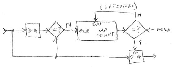
A vector of encoder push buttons / GPIO are presented to the input, and compared to the past input.  If new and old are not equal then the counter is reset.  If they are equal then the counter counts up.  When the counter hits the maximum the input is registered to the output.  If you think about it stopping the counter at max isn't necessary, but leaving that out makes it rather tricky.  This construct ensures that all inputs are stable for a period of time before they are sent on to the rest of the software, and the time period I picked is 25ms - you want the longest time here that you won't notice as a delay.  Obviously one flailing input could kill all the others, so we're assuming things are generally all quiet on the western front, luckily that seems to be the case.

For the rotational data from the encoders, I designed a highly similar stability construct which operates on the sampled clear-on-read register data.  A fast twist gives about 16 detents in about 0.1sec, so say 200Hz.  1/200Hz = 5ms, and in practice I found that a timer value of 3.3ms works well.  It's vitally important to enforce a minimum detent time if you are implementing a velocity speed-up, because glitches from a noisy encoder will be interpreted as fast spins, adding injury to insult.

On my third prototype the two lower two encoders which surely have the most wear (selecting voice and tooling around the UI) are kinda jumpy and do somewhat large reverses now and then.  I notice that after some "exercising" they get better, so it's clearly a contact wear issue at work here.  On one hand you want velocity so you don't prematurely wear out your encoders, literally spinning them to death, on the other hand velocity will bring out the worst in a worn encoder (rock & hard place).  It's been bothering me that so much basic conditioning, and worse quadrature decoding, is going on in the HW which ties my SW hands in terms of patching things up.  But I've come to feel this isn't quite so non-ideal.

In the FPGA hardware the encoders lines are individually linearly filtered with 2^14 width accumulators clocked at 180MHz.  The hysteresis width is 1/3 the width, so the minimum time the sneakiest glitch could sneak through is: 2^14 * 1/3 * 1/180MHz = 30us, or 33kHz.  Since a fast twist gives a detent rate of around 200Hz, and we need to sample and detect the quadrature events for each detent - say 4 times this absolute bare minimum or 800Hz.  33kHz / 800Hz = 41.25 or about 2^5 or 5 bits margin.  I upped the accumulator width to 16 but didn't notice the flaky encoders improve much, if at all.  But you can't be too careful with glitchy data coming from the outside world so I'm going to leave it at 16.  With this the FPGA logic utilization is 90%.

After trying several different approaches to rotational velocity sensing I settled on a linear decay:


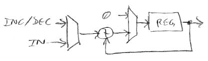
The sampled and stability debounced encoder data is presented to the input.  This is -1, 0, or +1 scaled up to 1/4th the width of the accumulator register.  If the input is non-zero it is added to the register, saturated (not shown), and registered.  Otherwise a fixed increment is added or subtracted from the registered value in order to drive it in the direction of zero.  For those instances where the increment value is too large and would result in overshooting zero the register is cleared to zero, and this is necessary in order to prevent oscillation.  Note that the output is the old accumulated value before the current input is added.  Most of the time the input will be zero, but when input pulses of the same sign come in close enough together the previous one will not have decayed to zero, so the new one will add to the accumulator.  Enough quick pulses will add up in the accumulator and saturate it, giving us a 4x velocity gain maximum.  Using signed accumulation here will tend to "knock down" the sum if the values that are coming in quickly are of different polarity and reduce the velocity value for that impossible (in a perfect world full of perfect encoders) and therefore error condition.  The absolute value of the velocity is taken, and 1/2 is added to this before it is quantized which is necessary in order to center up the velocity action.  Finally this is multiplied by the encoder -1, 0, +1 value in order to restore the sign and gate it, then it and the encoder value is added to a running total.

Another error condition I finally realized and dealt with is the ambiguity of the encoder rotation value -2 in the FPGA register.  When the hardware detects a clockwise detent it increments a two bit counter; counterclockwise detents decrement the counter.  A glitch can easily result in a count of two or more change between sampling times (which clears the counter).  Since the counter is modulo, two clockwise or counterclockwise counts will give the same result of -2, so I've added code to kill that whenever it is encountered by the software.

The above actions take place at the audio interrupt rate of 48kHz, which is firmly in overkill territory in terms of the required sampling rates.  In order to save real time I'm using a three bit counter to schedule the rotational processing of the 8 encoders one at a time, and do all sampling and debouncing only with encoder[0].  So the sampling and processing rate is 48kHz / 8 = 6kHz.

You haven't had your HW & SW ass properly kicked until you meet up with a gang of encoders in a dark alley.

[EDIT] Forgot to mention:  The GPIO and encoder input information is massaged as described above via the thread 7 interrupt service routine.  The otherwise continuous code in thread 7 is an infinite loop dealing with 1) the serial port command line interface which is used to interact with this human and the librarian software, and 2) the D-Lev user interface, which must process the input information further, scale the encoders for direct use by the software, update the LCD, etc.  How do you get the encoder rotation data from the ISR domain to the main thread?  What make this complicated is the unknown timing between the domains (if you know one is faster then you can rely on Nyquist guarantees).  The trick is to have no handshaking, just condition the data and store it, then let the other side read it and further condition it / detect changes as necessary.  Accumulate rotations and have the other side differentiate it, and as long as the modulo time isn't exceeded no data will be lost.  Rather like FIFO pointer exchange, it's likely a problem with only one simple solution.  In all things, whenever possible, feed-forward is the thing to pick, feedback the thing to avoid.

Posted: 2/14/2021 4:10:29 PM
dewster

From: Northern NJ, USA

Joined: 2/17/2012

Soft & Hard, Warm & Cold

Ran out of processor RAM (random access memory) the other day, which prompted a frantic search through the codebase for things to sacrifice, if only temporarily.  The band-aid I came up with in order to keep development limping along was to call the SPI EEPROM (serial peripheral interface electrically erasable programmable read only memory) read and write boot code subroutines from the general use RAM area, rather than copies of them (fortunately I already had an assembly construct that could do this).  The boot area consists of 512 bytes at the top of the total (whopping!) 16kB RAM.  The boot code itself is just over 256 bytes, and I'm confident I could get it a little under that, so I'm thinking of cutting the reserved boot space in half in order to claw back 256 bytes back for general use.  This would allow me to reserve a couple of knobs for the UI, each of which requires at least 10 bytes.  And, yes, I know this all sounds crazy in this day and age where RAM costs literally almost nothing, but the FPGA BRAM is tightly integrated to the processor, it's all I've got, and 16kB isn't exactly tiny when everything is hand crafted in assembly.

The boot process in any system is always a weird thing. "Bootstrapping" - pulling yourself up in the air by pulling on your bootstraps - is a colorful, yet descriptive term for it.  The D-Lev uses my "Hive" soft processor running at 180MHz in an FPGA, and the FPGA itself has an initialization or boot process, so it's even weirder than normal.  Power-up triggers an automatic FPGA initialization, or "configuration" in the parlance, where a small portion of the currently brain-dead FPGA hardware directs a separate EEPROM device to feed it a serial or parallel data stream containing the data necessary to program the zillions of switches in FPGA, thus connecting up the generic hardware within.  During this process the internal block RAM, or "BRAM", can be initialized to whatever you want, and I use this to automatically have a default or "golden" SW (software) load for the FPGA to run after the logic, and therefore the processor, comes alive.  Only thread 7 is allowed to initially run code, and at reset it vectors to the boot code.  The boot code reads the entire SW load in EEPROM in order to check its CRC32, and if the correct signature is found (the constant 0xDEBB02E3 if the load isn't corrupted) it goes ahead and reads the entire SW load again, but this time it transfers it to BRAM, overwriting the default SW.  If the signature is bad it just exits and runs the default SW.  To avoid "bricking" scenarios, where a misbehaving but otherwise valid EEPROM software load prevents the upload of new SW to the EEPROM, the boot code checks encoder pushbutton [7] before doing anything, and if it is pressed the boot code is exited to run the default SW.

In many systems there are several hierarchical levels of boot.  "Cold" or "hard" boot usually refers to a power-on type scenario, where all of the hardware is in a known state.  "Warm" or "soft" boot is usually one initiated either directly or indirectly by SW.  By "indirectly" I'm referring to the failure of SW to "stroke the dog" or otherwise keep a simple dedicated hardware sanity timer sufficiently entertained so as not to expire, causing a boot.  This setup is no guarantee of sanity because SW can be out in the weeds yet still be attending to the watchdog, but the mechanism usually boosts overall system stability in the face of the unknown, such as ESD or cosmic rays, or just plain badly written SW.  Unattended SW recovery can actually be a compliance requirement.

The D-Lev only has cold boot at power-up, and warm boot by writing to the processor reset register.  I could certainly implement an automatic warm boot, but there is no watchdog timer on the board.  I could probably implement a watchdog in the FPGA logic, but it would require an external connection to the FPGA configuration hardware.  As you might imagine, watchdogs tend to be problematic during development, resetting the board at the worst possible moment, interfering with SW installation, etc. so the hardware folks usually include a jumper that you can install to defeat it.  But unless I'm somehow forced to, I'm probably not going to implement an automatic warm boot.

It's tempting to overwrite / utilize the boot area for something like sample delay data storage, where the contents aren't going to be executed like code.  This would preclude a warm boot post SW upload, but one could instead just lock all the threads after an upload and then do a power-cycle to read it in.  I hope I'm not forced there as it somewhat reeks of desperation.  I've said this before when it wasn't quite so true, but the SW side is definitely winding down and feels 98% done.

[EDIT] Just thought of this and believe it would probably work.  It wouldn't reference any subroutines in the boot code for normal code (this is an awkward manual-override kind of thing in assembly) and would allow the utilization of the boot area for delay storage.  To upload a new SW load (all operations performed by the librarian SW running on a PC via RS-232):

0. Disable all thread interrupts and wait for all threads to park.  Thread 7 main remains alive to talk to the serial port.
1. Write the new SW load to EEPROM.
2. Write a new boot image to the RAM boot area.
3. Initiate a warm boot by writing to the reset register.

Step 2 is the only new step, and might actually make things safer because it would provide an extra level of assurance that the boot code is indeed good.  All of this stuff feels vaguely like a high-wire act with no net.

Posted: 2/16/2021 2:10:12 PM
dewster

From: Northern NJ, USA

Joined: 2/17/2012

Geometric Curvature & You

Scaling your knobs can be an amazingly deep issue.  Unlike most other equipment I've seen, the knobs on the D-Lev are almost all binary in terms of detent min/max ([0:31], [0:63], [0:127], [-31:31], etc.) which works well in terms of feeding the raw knob values to underlying binary math and producing a binary result.  This also gives a nice stepping assortment of knob ranges, so if [0:31] feels too tight or granular then you can go to [0:63] or wider.  This probably seems a little weird to those steeped in base 10, but one can only bow to awkward convention but so much.  I'm a loner.

Most of the real work of scaling these knob detent ranges comes down to finding a good curvature match for a given preset parameter.  Often you're extremely interested in the dynamic range between the two ends of the knob, and the distribution between those ends.  In many cases the range is the easy aspect to wangle, and the distribution not so obvious.

You may have heard maths types speaking informally about how certain equations "go" - and by this they often mean how quickly the results changes when fed a linearly changing input.  Some functions such as log inflect more slowly than linear, and so form a convex graph.  Many inflect faster than linear and form a concave graph, and these are the ones we're most interested in for knob scaling.  In terms of "going" or curvature, here is a ranking from slowest to fastest (this is a little like ranking infinities):

-2. logs
-1. roots
 0. linear
 1. powers / polynomials
 2. exponentials
 3. inverse / anything asymptotic

Up until now I've employed 0 thru 2, but yesterday I found myself wanting to linearize the pitch correction "span" parameter.  The logic uses multiplication to control the slope of a line from 45 degrees to ~90 degrees, and after much doodling it was clear that an inverse was what I was looking for.  I thought it might require TAN (or ATAN) but it's the length of the opposite side of the angle that needs to be linearized, not the angle itself.  Integer inverse takes an unsigned int and produces an unsigned fraction, and vice versa.  I/O resolution is always an issue with inverse: the more significant bits you feed it the fewer you get back.  Since the linear knob resolution is limited to 8 bits, it makes sense to treat it as a UINT, which would then give the output UFRAC the maximum resolution.  But what about zero input?  In lieu of infinity, my inverse function returns -1 here, or the maximum possible value.  What about an input of 1?  The inverse function also returns -1 here, which is the maximum possible fraction.  This is clearly a problem, but multiplying the input by 2 or more differentiates these two cases, and allows one to use signed shifting of the (unsigned) result to increase the value of the zero input case, making it more infinity-ish.

There may be instances where we want the curvature of inverse but not the gradual [2:1] output range at the end.  For this we can simply subtract a small number from the answer to increase the dynamic range to whatever we need.  For example, subtracting 0.5 from the answer makes the upper range cover [1.5:0.5] or [3:1], subtracting 0.75 yields [1.25:0.25] or [5:1], etc.  Subtraction also increases the end-to-end dynamic range, which can be useful.  I also use this trick on exponent scalings, pulling the result to zero.  One can also flip the input / output (*-1) in order to reverse things or to produce a convex inflection.

Since the ear's response to both volume and pitch are logarithmic, it's not too surprising to find exponentially scaled knobs / frets / strings in a musical instrument, and indeed the EXP2 scaling has turned out to be quite a popular one in the D-Lev.  You can certainly do it all very efficiently with simple powers and polynomials, but it's nice to center the knob detent range around the most useful nominal settings, leaving the ends for turning things off / making things go crazy, and that may require scalings which have more get-up-and-go.

You must be logged in to post a reply. Please log in or register for a new account.