555 volume control

Posted: 6/2/2012 12:33:47 AM
invisiblejelly

Joined: 3/18/2012

http://www.techbites.com/myblog/ingenuity/Page-7.html

The picture below comes from the above article/blog which is closed for maintenance but should be availiable later sometime.Below is the circuit which uses 555 volume control for the theremin in the EPE 04 issue by Robert Penfold.I wonder if this could be adapted for the EW standard.It uses pulse width control to control current at about 25 khertz.


Posted: 6/2/2012 12:48:30 AM
FredM

From: Eastleigh, Hampshire, U.K. ................................... Fred Mundell. ................................... Electronics Engineer. (Primarily Analogue) .. CV Synths 1974-1980 .. Theremin developer 2007 to present .. soon to be Developing / Trading as WaveCrafter.com . ...................................

Joined: 12/7/2007

Looking at the schematic, I would guess that it is hugely inferior to the volume circuit already in the EW standard.

When I say "hugely", this is an extreme understatement - sensing range will be extremely limited, and linearity will be appalling.

Given the choice between Penfold and Moog, I would choose Bob Moog's designs any day! I really dont rate Penfold, wheras Bob was the master!

"I wonder if this could be adapted for the EW standard"

Simple answer - NO!

Fred.

Posted: 6/2/2012 2:03:54 AM
RS Theremin

From: 60 mi. N of San Diego CA

Joined: 2/15/2005

invisiblejelly if the EtherWave Standard already has a volume control why are you looking for another one?

Are you interested in building a very responsive independent stand alone theremin volume control?

Posted: 6/2/2012 6:48:39 AM
invisiblejelly

Joined: 3/18/2012

RS Theremin ...Yes I'm interested in volume control that doesn't have coils and that is linear and responsive surely it's not that hard?.The above 555 schematic, since it is a pulse width control circuit, could I thought be used to control the current to an LED (or more than one) so you could use it for optical volume control.

http://i298.photobucket.com/albums/mm270/michaelpudney/thereminaudiovolumecontroliraudiolink20252G003-0.jpg

Even a simple ir audio link like the above might be able to be adapted for a theremin volume control...I'm not quite sure how though...


Posted: 6/2/2012 2:21:03 PM
RS Theremin

From: 60 mi. N of San Diego CA

Joined: 2/15/2005

I used this method in the early days of my theremin research. The CdS cell is removed from bathroom nightlights. These are common and still sold here in the states though the industry I think wants to get rid of CdS. R2 may not be necessary.This approach works excellent yet is not as fluid or sensitive in range as the RF loop.  I can do better but you said no coils! (-'

Using the CdS cousin a photo transistor is crisp in response but much more susceptible to 100hz/120hz room lamp flicker. Halogen light works the best for smooth light powered by the wall. Through a transistor the signal must be below .6v p-p if memory serves me correctly.

Posted: 6/2/2012 9:20:08 PM
FredM

From: Eastleigh, Hampshire, U.K. ................................... Fred Mundell. ................................... Electronics Engineer. (Primarily Analogue) .. CV Synths 1974-1980 .. Theremin developer 2007 to present .. soon to be Developing / Trading as WaveCrafter.com . ...................................

Joined: 12/7/2007

Jelly - When you say something like:

"Yes I'm interested in volume control that doesn't have coils and that is linear and responsive surely it's not that hard?."

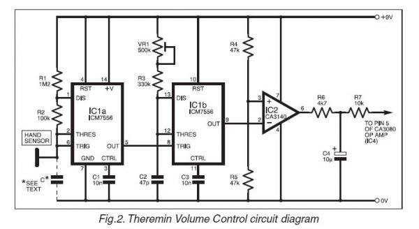
Do you think Bob Moog put expensive coils into his design if it was a "simple matter" to design a responsive linear volume control without them? Do you think that he just chose coils costing about $2 deliberately to up his costs, rather than using a simple 555 circuit costing <50c ?

I am not trying to wind you up here - Just trying to get you to think about the realities. I am not saying that no person will ever come up with a clever, simple way to achieve what you are after... But I am saying that the 555 circuit you presented is NOT CLEVER - It is rubbish, will have low sensitivity and appalling linearity - and its nowhere close to the quality of the design in the EW.

Anyway - I wont be engaging in this topic anymore.. I was once foolish enough to think that theremin design was 'simple', that I never needed inductors, and that an inductorless theremin which knocked the cr*p out of the old technology would be in my hands in months - I had been an electronics design engineer for 30 years, and I never saw the inherent complexity within what looks like such a simple design..

Good luck!  ;-)

Fred.


Posted: 6/2/2012 9:35:54 PM
FredM

From: Eastleigh, Hampshire, U.K. ................................... Fred Mundell. ................................... Electronics Engineer. (Primarily Analogue) .. CV Synths 1974-1980 .. Theremin developer 2007 to present .. soon to be Developing / Trading as WaveCrafter.com . ...................................

Joined: 12/7/2007

Oh, one final thing..

Dont trust circuits which are published on the WWW ! Go for tried and tested circuits / kits until you know what you are doing.

The IR link schematics are a joke.. think about it, what happens when a transistor is reverse biased (NPN, emitter more +ve than base) ? What happens when you put AC audio via a resistor directly to the base of a transistor? What (apart from anything else) does Vbe mean to you?

If you cannot see what I am saying, you either need to buy kits, or to read up on electronics before you touch anything!

Fred

Posted: 6/3/2012 3:28:58 AM
invisiblejelly

Joined: 3/18/2012

Thankyou RS Theremin...I don't see why your circuit couldn't be used with that 555 timer one as it uses pulse with mod.at 25khertz and that wouldn't put 100 or 120 hertz into the sound of the theremin...whether it would work or not might depend on how many LEDS one uses...and the resistances of the lit and unlit photo resistor(s) or photo transistor(s) etc...Of course I may be setting myself up to be appalled by the terrible response of the whole setup...but I'll still give it a go sometime.

Posted: 6/3/2012 3:48:45 AM
invisiblejelly

Joined: 3/18/2012

Thanks Fred for your advice I know it comes from a good place ie having concern at me be appalled by those bad circuits after making them.I don't have much experience at electronics but I have done a little bit of tinkering both with the EW standard which I have altered by putting 30 or so extra diodes in wired as caps in parallel and a couple more in different places...which is something an engineer like yourself would find silly(I suspect)...I did it and now have a better sounding theremin with a better bass...to my ears anyway.I have also tinkered with Mr Harrison's minimum theremin and I put an LED in the mixer and have improved the bass and general tone...hear it below.

http://soundcloud.com/invisiblejelly/minimum-theremin-with-led2

here below is a picture from the top of my minimum theremin showing the glowing LED.

http://i298.photobucket.com/albums/mm270/michaelpudney/minimumthereminwithled.jpg

below is a picture of my minimum theremin looking side on.

http://i298.photobucket.com/albums/mm270/michaelpudney/minimumthereminwithtincanaerialinplastictube.jpg

It is housed in a plastic tube and has a tin can as an aerial which fits in the tube..it has a 1mH coil connected to the tin can and the linearity over about 3 octaves is reasonable but there is quite a bit of drift with this circuit.

Anyway thanks Fred for your insights and help...I do find your posts all very interesting...I just love messing with theremins...it is a great hobby..I still got much to learn.


Posted: 6/3/2012 10:22:15 PM
FredM

From: Eastleigh, Hampshire, U.K. ................................... Fred Mundell. ................................... Electronics Engineer. (Primarily Analogue) .. CV Synths 1974-1980 .. Theremin developer 2007 to present .. soon to be Developing / Trading as WaveCrafter.com . ...................................

Joined: 12/7/2007

invisiblejelly,

This is just a quick pointer to demonstrate the kind of crap that is appearing on the WWW as schematics.. This is a crude simulation of the "Simple audio IR link" circuit:

And the resulting waveforms:

The red waveform is current through the LEDs! - LOL, usable as a gross distortion box - perhaps - but the waveform bears absolutely no resemblance to the input audio!

LTspice is a good free simulator, ideal for gaining basic understanding of circuits, and for quickly testing internet schematics to see if they are rubbish (more than 50% are absolute crap).

Links to LTspice and tutorials for it etc can be found here.

Fred.

You must be logged in to post a reply. Please log in or register for a new account.