RCA - Signals / Waveforms etc - "Real" .

Posted: 10/11/2012 7:25:48 PM
FredM

From: Eastleigh, Hampshire, U.K. ................................... Fred Mundell. ................................... Electronics Engineer. (Primarily Analogue) .. CV Synths 1974-1980 .. Theremin developer 2007 to present .. soon to be Developing / Trading as WaveCrafter.com . ...................................

Joined: 12/7/2007

I have started this thread as a place where:

A:) Questions / Answers / Advice etc can be exchanged regarding obtaining real-world data from actual theremins designed or REALLY based on designs by Lev Termen (RCA, Claramin etc, and tube clones of these)

B:) Where results, or links to results / images / recordings etc can be placed.

Other than discussion relevant to obtaining the above, I would prefer it if this thread was not used for technical analysis of any results obtained - The exception to this perhaps being advice / requests for data which is "missing" and arguments for obtaining such data.

I will start by moving a posting replying to Hobbs who is hoping to do some probing.. ;-)

" Send me the marked up schematic w/ the test points ( or even a verbal list- ie: grid of v3 ;or  junction of T6 and r15)      and Ill get started on "catching some waves" for you. "

Here we go ;-)

Refer to Art Harrisons drawing Pg 2, Rev 11, 3-04-04 :

V2 = 224 Tetrode mixer, V1 = 227 Triode Pitch Oscillator, V3 = 227 Triode Ref oscillator, V4 = 227 triode Audio preamplifier, V7 = 171A Triode Audio power amplifier

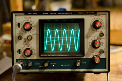
Plate of V2 in as much detail as possible. The mixer waveshape should be visible here, even if as an 'envelope' containing HF.*

GC (cap) of V2 = Waveform from Reference Oscillator - Ideally noting amplitude and any DC offsets.

SG of V2 = Waveform from Variable Oscillator - Ideally noting amplitude and any DC offsets.

Grid of V4 = Input to pre-amp.

Plate of V4 = Output from Preamp*

Grid of V7 = Audio output / Speaker connector.

Then a high quality (miked) audio recording from the speaker covering full frequency and volume ranges would be the icing on the cake! ;-)

*These points may not give representitive voltage waveforms, as they are current sinking from a low-R high-L load - But nonetheless checking the voltage waveforms should give useful data.

Fred.

Posted: 10/11/2012 8:35:49 PM
w0ttm

From: Small town Missouri on Rt 66

Joined: 2/27/2011

This was copied from another thread. While directed at Chobbs, I believe this relevant to anyone attempting to analyze a tube circuit. If anyone can think of more to add, all comments and / or corrections are welcome... Rob


The goal is to protect the scope front end from the high voltage and avoid loading the high Z bits. Grids are the most sensitive to this. The cap blocks the DC, and series resistance reduces loading.

The more series resistance, the better, within reason. Several megs would be nice. I have a special 10 meg, high voltage resistor that was used in a voltage divider to measure plate voltage in a very high powered tube amplifier.

If you listen to your theremin and detect very little or no difference in the sound with the probe on or off, then you are good. I suspect that there might be some minor frequency shifts in some probes. A few Hz should be OK.

Check calibration with a known voltage source and make a note of any variation. Almost every scope I've seen has a handy output on the front for just such a use. Mine has a 5 volt square wave, but any low voltage AC source will work, such as a 12 volt transformer.

My scope is rated at 300 volts DC input, and I have probes with a nifty little 10 X switch that should let me probe most tube circuits directly. I never do. I always insert a lot of resistance.

Scope bandwidth is important. You can still see the wave forms if the bandwidth is too low, but calibration goes out the window. Being a dual trace, your scope should at least have a 5 MHz bandwidth, probably more. The lowest bandwidth dual trace I've seen went to 10 MHz, and I've used it to view 30 MHz signals.

A word on safety.....

High voltage wants to kill you. One of the things I do is probe with one hand, with the other hand in my back pants pocket. This makes it impossible to have current flow from one hand to the other, with my heart in the middle. It's still possible to get a shock, but the results are much cussing, not death. Also, stand on something insulated so current can't flow from your hand to a foot, with other important body parts in it's path.

Be aware of your surroundings. If you do get a shock, you are likely to jump, and possibly bash into something that will hurt even more, or knock your chassis off the bench.

Posted: 10/12/2012 8:08:40 AM
FredM

From: Eastleigh, Hampshire, U.K. ................................... Fred Mundell. ................................... Electronics Engineer. (Primarily Analogue) .. CV Synths 1974-1980 .. Theremin developer 2007 to present .. soon to be Developing / Trading as WaveCrafter.com . ...................................

Joined: 12/7/2007

High voltage wants to kill you

Thanks for that reminder, Rob - and for your clear sensible advice. The worst current path is Right arm to left leg, then right arm to left arm - But as Rob has said, any shock can cause severe injury or even death through its concequential effects.

We want data on the waveforms - but any injury would be far too high a price to pay for this data.

So please everyone, If you arent sure you can undertake this without endangering yourself, DONT DO IT!

And if you are sure - be unsure, and take every precaution suggested by Rob!

Fred.

Posted: 10/12/2012 3:52:39 PM
Chobbs

From: Brooklyn,NY

Joined: 12/1/2009

Guys-    (a little embarassed...) but most of my experience with the scope has been more visual... ( "ooh, I can see what I hear!" )  I know the basics but  to get you guys  stuff like dc offset - Im going to need to take a short  oscilloscope tutorial.   Anyone have some good suggestions?

Posted: 10/12/2012 6:07:19 PM
w0ttm

From: Small town Missouri on Rt 66

Joined: 2/27/2011

Since you live in the US, a phone call makes sense.

randkg (at) att.net

Drop me a note, and we can swap numbers and arrange a good time to call.

I work most evenings.

Posted: 10/14/2012 3:07:04 PM
Chobbs

From: Brooklyn,NY

Joined: 12/1/2009

Guys (w00tm- just sent you this message)

I started poking at the RCA last night and had some frustrating/ interesting results.  This may be hard to explain....
So ....regardless of where I test- Im getting the same wave....  and any freq variation, either from testing the oscillator or even the speaker output- appears as tiny waves on the large wave.    Also the scope starts to see the large unchanging wave  even before I connect the probe (RF interference?)    By reducing the volt and time constants I can 'zoom' in a bit but it gets pretty faint and beam wants to be  diagonal...   Am I doing something wrong?  Im using Fred's recommended probe clip      Scope appears to work fine for testing other stuff and I first used this scope  for setting up my keppinger (unfortunately,its not here now), so I know I can get it to read  a tube theremin...

Posted: 10/14/2012 4:30:12 PM
FredM

From: Eastleigh, Hampshire, U.K. ................................... Fred Mundell. ................................... Electronics Engineer. (Primarily Analogue) .. CV Synths 1974-1980 .. Theremin developer 2007 to present .. soon to be Developing / Trading as WaveCrafter.com . ...................................

Joined: 12/7/2007

Hi Chobbs -

What is the frequency of this predominant sine wave? - Does it change as the audio frequency changes?

I am wondering if it is something simple like a ground loop problem - is the 'scope solidly grounded to the theremins ground? One needs to ensure that ground currents do not travel through the screen of the lead - as in, dont connect the scopes grounding clip if one gets these kind of problems - but have the ground connected with a seperate wire.

Is this main sine wave at mains frequency (50 / 60 Hz) ? This would indicate a problem with the probe assembly - Easy way to check is to turn the theremin off, and see if you get the same frequency wave when you touch the probe.. if you do, then its mains hum, and you need better screening and/or earth connection.

At a more complex level, the inductance of the probe capacitors could affect things - but not at audio frequencies, and I think only slightly at 173kHz.. So I dont think its that.

What are the settings on your scope - If you can tell us this, and how many cycles of the sine appear, and how many horizontal divisions one cycle of the sine spans, we may get there..

Good luck,

Fred.

Posted: 10/14/2012 5:29:37 PM
Chobbs

From: Brooklyn,NY

Joined: 12/1/2009

fred -  it is set @  10v and 2ms  -  wave appears to be about 60v and 4ms peak to peak. 

the wave appears exactly the same at different points throughout the theremin(except ground) BTW this is a 2- prong-er  AC only no ground on the power cord.

when I test something -either the audible freq at the speaker jack or an oscillator) the main wave does not change size or shape but the tested signal appears as tiny visible waves on the predominant one (looks like the main wave gets fuzzy)   Also behaves the same with or with out the separate probe clip to ground.

With theremin off, when I touch the probe- there is a slight bump in the trace but pretty much goes back flat.

With the theremin on, when I touch the probe there is a visible wave that grows with its proximity to the theremin chassis.     (I was wrong- nothing appears  on the scope when the theremin is on and I am not touching the probe)


Posted: 10/14/2012 9:38:32 PM
FredM

From: Eastleigh, Hampshire, U.K. ................................... Fred Mundell. ................................... Electronics Engineer. (Primarily Analogue) .. CV Synths 1974-1980 .. Theremin developer 2007 to present .. soon to be Developing / Trading as WaveCrafter.com . ...................................

Joined: 12/7/2007

 "wave appears to be about 60v and 4ms peak to peak." _Chobbs

4ms = 250Hz - So whats producing a strong 250Hz radiating signal ? What is the audio frequency you are hearing from the speaker? What happens if you mute the speaker (either with the mute switch if you have one, or by putting a lead over the volume antenna) ? Is the speaker one of these weird AC powered things (RCA 106)?

I believe your mains supply is 120V 60Hz..

Sorry to be asking questions rather than giving answers! - But I dont have a clue about whats going on! - If it was something "sensible" like 60 or 120Hz (frequency of 1/2 wave rectified mains) or even somewhere 'round 20kHz ( taking Uncle Howies hypothesis of a 20kHz blocking action - a hypothesis for which I have not found any evidence - but which, because it is Howie, I must deem a possibility ) - but 250Hz everywhere, that I really cannot explain.

My only suggestion I can think of right now is for you try a different probe - connect four 330k small (<= 1/4W) resistors in series, and omit the capacitors.. This is not as safe as having safety class capacitors in series, but should be ok ( Dont replace the 4 resistors with one higher value resistor - The idea is that the voltage  across each resistor is reduced if the resistors are in series, making them less likely to fail - also, if any do fail in short-circuit mode [unlikely, but possible] the others will be there to prevent danger).

You will need to check the probe against a known signal source - there is usually a calibration output to facilitate this.. note the scaling factor (for example, if a 1V calibration shows as 0.4V, multiply all other readings by 2.5)

Fred.


Posted: 10/18/2012 1:24:15 AM
Chobbs

From: Brooklyn,NY

Joined: 12/1/2009

Ok- mystery solved.  "The Phantom Wave" was RF interference.  I got rid of all the gator wires and the chain of twisted up resistors - even the spring wire clip on the probe....and  I made a longer shielded wire with a clip. Voila!


I could only get three of thetest points  at the moment.  The other 3 are more difficult to access to access externally... and this thing is a mother to bench test.   I was considering striping some wire and wrapping a few turns around the coresponding tube pins.... Illl let you guys know how it goes.
for now here are some images:

Control Grid of V2 (scope @5v/.5uS):


Screen grid of V2(@5v/.5uS):


and Grid of V7 / Audio Out (scope@10v/.1ms- playing approx 440hz at (mostly) full volume):

The instrument is not fully warmed up and was waaay to close to my bench....it is not necessarily displaying the ideal tone. Looks thin- the wave had a bit more of the 'cursive r'  shape at lower freq's, but it was really hard for me to keep the pitch stable, adjust the scope level, and take a picture    I try again when I get more time

You must be logged in to post a reply. Please log in or register for a new account.