Tell us about your experience with Open.Theremin

Posted: 11/21/2013 10:41:07 PM
dewster

From: Northern NJ, USA

Joined: 2/17/2012

Hi Urs,

Thanks for not taking offense at my technical nitpicking, I suppose I'm too passionate about the subject of Theremin circuit design.

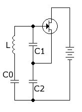
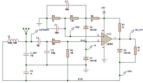
Since you are using CMOS logic in your oscillators, have you had a look at the Andre Smirnov circuit?  http://asmir.theremin.ru/tsensors_sch.htm

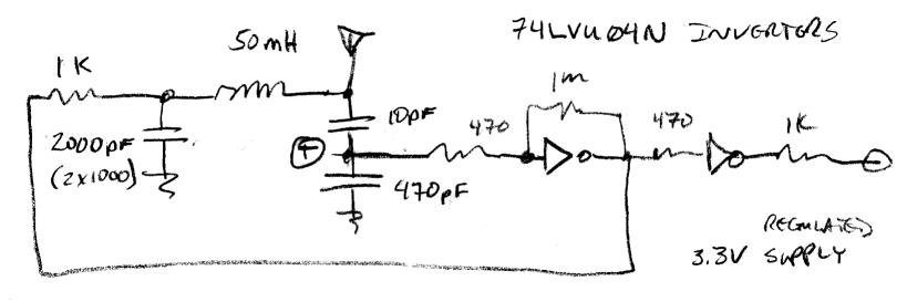
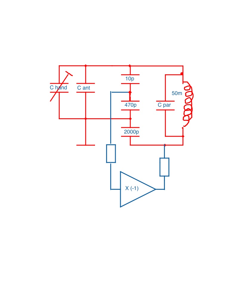
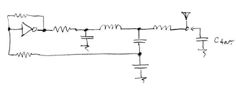
Until I really understood inductors I couldn't say the circuit made a lot of intuitive sense to me.  Now that I do it strikes me as quite elegant, but I think it can be improved.  The 6.2k 470 pF RC network gives a ~90 (?) degree phase lag, the inductor another 90 lag, and the inverters a further 180 degree lag, which in a loop gives oscillation.  The 6.2k limits current drive, and therefor sets voltage swing at the antenna - I've had good results with 470 ohms here.  The RC also kills a lot of harmonics in the drive which is a good thing.  I'm not sure I would use an auto-transformer as it couples in the drive, but it probably does ensure start-up of oscillations.  Instead, I'd try to use an independent small winding on the drive end of a Bourns 6300, and not load it down too much so as to keep sensitivity as high as possible.  I would also add ESD protection to the environmentally coupled CMOS I/O (Littelfuse SP721 or similar) for long-term reliability.  Finally, the string of 5 inverters seems kind of unnecessary, and I'd probably go with 74LVU04N which has much better drive, and use a 1M or so feedback resistor for stability and auto biasing about the theshold.  (The unused 4069N inverter could have been ganged in parallel with the one doing the driving to get more drive current.)  (Also: there is no requirement for symmetrical values with the two 470pF caps, if that works out best then fine, but it often doesn't, and you might actually want some capacitive voltage dividing going on here.)

The choice of inductors is a hugely critical factor IMO, with very few commercial offerings up to the task.  Closed (i.e. no air gap) ferrites are unfortunately pretty much out due to temperature dependencies.  The first defense against the need for aggressive TEMPCO is to avoid the use of temperature sensitive components in the first place.

I haven't looked at your software, but do you have a way to alter hand / note spacing?  The general consensus here is that the wider the spacing the easier it is to play (lots of "playable octaves" are kind of like point-and-shoot megapixel counts - where more is often less).  For my own designs I will be doing a log2 conversion on the pitch data to facilitate this (as well as linearization), and "undo" this with an exp2 function at the input to the NCO.

[EDIT] A few more thoughts regarding the Smirnov circuit above.  The frequency dependent delay of the RC is problematic, as it means the circuit probably has to be tuned any time there is a change in bulk antenna capacitance (which is accomplished in the circuit via a ferrite slug in the coil).  Also, the inverter string delay is significant and so I believe is being used as an element in the 360 degree phase loop, and transport delay through CMOS logic is highly temperature dependent.

Posted: 11/23/2013 2:56:42 PM
gaudi

From: Switzerland (CH)

Joined: 8/6/2010

Hi dewster

Have met Andre twice and admire his work a lot. I have tried to build his oscillators before without to much success. I would like to use small (and affordable) SMD coils. Tried also with handwound coils, even 3D printed the exact core (see here). How can I simplify the schematic with the double coil (W1 / W2) into a SMD 74LVU04N design? And (sorry my ignorance as I am a self tought theremin builder) what is the capacitor and coil in series with the antenna good for? The several inverters in series help to get a clean square signal.

Urs

Posted: 11/23/2013 3:06:34 PM
gaudi

From: Switzerland (CH)

Joined: 8/6/2010

Concerning your question: Yes it is possible to adjust the note spacing / full range octaves on the open.theremin by setting the manual calibration frequency higher or lower - as Roy noted in his discription. - The manual calibration is not on zero-beat but about 500 to 800 Hz higher and then the software does the calibration to zero, stretches the range wider and does some filtering.

Posted: 11/23/2013 7:59:16 PM
dewster

From: Northern NJ, USA

Joined: 2/17/2012

gaudi / Urs (how should I refer to you here?):

"I have tried to build his oscillators before without to much success."

I haven't tried to replicate his oscillators, but have used many of the same elements.  What difficulties did you encounter?

"I would like to use small (and affordable) SMD coils. Tried also with handwound coils, even 3D printed the exact core (see here) ... And (sorry my ignorance as I am a self tought theremin builder) what is the capacitor and coil in series with the antenna good for?"

Interesting.  Well, after some analysis, experimentation, and modeling, I've come to the (my own) conclusion that Theremin oscillators, both digital and analog, can be designed simply and effectively by thinking more in terms of the "EQ" coil (the coil in series with the antenna) than the coil in the tank.  In fact the coil in the tank can likely be dispensed with entirely.  There is an argument to be made that the interaction of the tank and EQ coil, if adjusted just right, increases playable linearity near the antenna - I think this is probably true, but IMO the effect is weak and much too fiddly - much better to address linearity in software IMO. 

The EQ inductor then resonates with the antenna capacitance, which gives you a fairly high Q scenario if you use a high Q coil (air core coils are usually quite high Q) and don't load it down.  I firmly believe (opinions differ) that this is the primary resonance you are interested in.  The job at hand then is to properly detect and stimulate this resonance, which an extra winding can do (or a capacitive divider, see below). 

I understand how you want to use inexpensive SMD components here, but the closed magnetic type (no air gap) will likely be too temperature sensitive because the ferrite itself usually is.  And you want to get the antenna side away from your digital circuitry, so you might as well go with hand wound air cores, or Bourns 6300 with an additional winding, or similar.  You might be able to use an IF or similar transformer on the board and couple this to a Bourns 6300 but I'm not currently looking at this scenario so it would take some experimentation on your part.

The series capacitance is considerably larger than the antenna capacitance and so is more there to kill lower frequency interferers like 56/60 Hz hum and such (the value isn't critical but I think I'd use something larger than 47pF).

"How can I simplify the schematic with the double coil (W1 / W2) into a SMD 74LVU04N design?"

I'd start out breadboarding.  It's not the absolute ideal, but perhaps this circuit I used to measure hand capacitance can get you going:

It gives ~127V p-p voltage swing at the antenna and draws 7.5mA from a 9V battery regulated down to 3.3V.  By altering the inductor value and the 2000pF capacitor value it can work at just about any frequency you want.  If you need more sensitivity just stick another identical inductor between the antenna and the circuit; add a series capacitance to reduce hum.  The voltage divider knocks the antenna voltage swing down and unloads the sensing, and you want to make sure the swing as presented to the input of the inverter is kept safely within the supply limits by adjusting the 1K and/or the 470pF accordingly.

-----

Take this (and pretty much everything I say here) with a grain of salt though because, unlike you, I haven't actually put any Theremins into production (i.e. put my money where my mouth is).  And unlike others here I haven't progressed beyond a pitch only prototype.

Posted: 11/23/2013 9:39:51 PM
Thierry

From: Colmar, France

Joined: 12/31/2007

dewster, your circuit has IMHO nothing to do with your mentioned "EQ" or "series" tank. What you are showing is a simple Clapp-Gouriet oscillator with a "normal" parallel resonant circuit. I allowed to draw it in a different manner to make it better visible:

(sorry for the bad quality, just quickly scribbled it on the iPad...)

Posted: 11/23/2013 10:27:00 PM
dewster

From: Northern NJ, USA

Joined: 2/17/2012

Like this?  (http://en.wikipedia.org/wiki/Clapp_oscillator)

My oscillator doesn't have a capacitor (C0) in series with the inductor.  What is Cpar in your drawing (parasitic perhaps)?

Adding and EQ inductor increases the sensitivity and turns the construct into a high Q 5th order LPF (RC + LC + LC) with feedback to make it oscillate:

I really don't want to get into a pedigree war over what topology to call something, that can be instructive to some degree but also endless if no consensus is formed.  Back before I knew better I called my topology "series tank".  And by chance that isn't entirely incorrect even now that I know better IMO, because the primary resonance IMO is with the series EQ & antenna capacitance IMO.

I believe all analog oscillators are one or more delay elements with feedback of some sort, and can be analyzed to a first order from a phase shift through the loop perspective.  It's nice to give credit where credit is due, but sometimes that can cloud the issue.

Posted: 11/23/2013 10:38:38 PM
Thierry

From: Colmar, France

Joined: 12/31/2007

Cpar is the parasitic capacitance. Your oscillator has (as the Clapp-Gouriet-Oscillator) basically 3 capacitors in series, like the Colpitts has always 2 in series. The resulting capacitance of these 2 or 3 capacitors (plus parasitic capacitance) is in parallel with the coil. The points where you pick up the oscillation and where you feed it back don't have an influence on the principle, they are rather selected following impedance considerations, together with the dividing ratio of the capacitors.

No need for a pedigree war. It's simple and obvious. :-)

Posted: 11/23/2013 11:24:09 PM
FredM

From: Eastleigh, Hampshire, U.K. ................................... Fred Mundell. ................................... Electronics Engineer. (Primarily Analogue) .. CV Synths 1974-1980 .. Theremin developer 2007 to present .. soon to be Developing / Trading as WaveCrafter.com . ...................................

Joined: 12/7/2007

[Sorry folks - this aint really about open.theremin - its a technical diversion, hijack at worst, a bit OT at best! :-]

Hi Dewster -

Just been playing with simulations of your oscillator for a new analogue topology I have been thinking about - ok, changed the inverter for a 393 comparator, as funny things happen with some of my simulators digital models (I must construct my own models to get reliable mixed signal simulations) -

Its really good! - With a 10mH inductor and added 10pF antenna capacitance, theres a 200V P-P (70V RMS) on the antenna, ~305kHZ, and 1pF change gives about 5.5kHz difference..

ok - no linearization.. but I think I have a simple answer for that ;-)

I like it! - its simple and looks really stable.

Some pics:


Ignore the "noise" on the bottom of the FFT .. Also, the complexity 'round the 393 is just force of habit - I keep all inputs to these parts below 2/3 the supply, as I have had them flip into strange operation when the inputs get "too" close to the supply - this protection stuff is useful for ESD anyway.. although I still usually go a lot further and would split R4 into 2x 1k, and connect a neon to ground from there... pedantic! ;-)

Posted: 11/24/2013 12:24:02 AM
FredM

From: Eastleigh, Hampshire, U.K. ................................... Fred Mundell. ................................... Electronics Engineer. (Primarily Analogue) .. CV Synths 1974-1980 .. Theremin developer 2007 to present .. soon to be Developing / Trading as WaveCrafter.com . ...................................

Joined: 12/7/2007


[Sorry folks - this aint really about open.theremin - its a technical diversion, hijack at worst, a bit OT at best! :-]


Regarding the war..

I just ran the simulation without the 2000pF capacitor (as in, I removed that C but made No other changes), and it ran fine, at almost exactly the same frequency -

IMO, this looks a lot more like a series resonant oscillator than any of that other Clapp! - Apart from Cpar, there is only a path through the inductor and the series capacitors, and this capacitance with the inductance give the expected series resonant frequency.

;-) But what do I know? I cant even recognise a SAH when I see one!  LOL ;-)

Ok - few more tests - I removed the two input capacitors (10pF and 470pF) - so now there is only the inductor, its tiny Cpar, and the antenna capacitance.. I had to connect directly to the input and mess with the input resistor values, but these dont influence anything relevant.. Its not as nice without these C's but..

The oscillator RUNS! - It IS NOT a load of CLAPP! - its a damn SERIES RESONANT OSCILLATOR.

Posted: 11/24/2013 1:29:53 AM
Thierry

From: Colmar, France

Joined: 12/31/2007

It naturally runs when you remove C3 and C4. Then there is the capacitive divider formed by C_ant and C5 in parallel with the coil, a simple Colpitts oscillator... still no series resonance... there is a phase shift of 180° between V_drv and V_ant.

You must be logged in to post a reply. Please log in or register for a new account.