Can anyone identify this Theremin?

Posted: 8/25/2014 4:40:31 AM
krellmusician

From: Hell's Quarter Acre, New England, USA

Joined: 12/7/2013

Help, please...

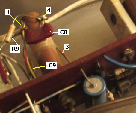
Doing final reassembly of this Theremin, one of the wires to the coil attached to the volume plate became disconnected from the coil. When I carefully (I thought) peeled off the electrical tape insulating and reinforcing the coil connections to locate the end of the winding to reconnect, the other wire came off. I now have a coil with very fine wiring and no indications as to where the winding ends are that I can reconnect to the wires from the board. Below is a picture of the coil as it existed before I initially disassembled the device.

I figure the proverbial snowball in Hell has a better chance of restoring this coil to function than I have at this point, so the questions I have are these:

(1) Has anyone reading this ever performed this kind of restorative surgery such that s/he would know what to do (even to the point of doing it if I sent the coil)?
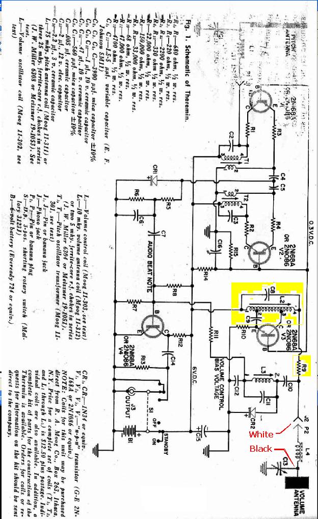
(2) If such an effort is not worth attempting, is it possible to suss out the likely inductance value and other characteristics of this coil so that I could try to find a replacement?
(3) Assuming option (2) is viable and my best shot at getting this working again, and the coil properties can be determined or at least estimated, where is the best place to look for a replacement?

Thanks in advance for your time and any help you can provide. I really want to get this instrument functioning.


Edit:  I am going to try to post picture that will show the original coil in situ, including the connections to the rest of the circuitry.


Posted: 8/25/2014 6:07:10 PM
FredM

From: Eastleigh, Hampshire, U.K. ................................... Fred Mundell. ................................... Electronics Engineer. (Primarily Analogue) .. CV Synths 1974-1980 .. Theremin developer 2007 to present .. soon to be Developing / Trading as WaveCrafter.com . ...................................

Joined: 12/7/2007

Hello Krell,

No photo is showing..

I have done surgery on IF transformers and other coils, but there's no guidance I can really give - You want a microscope or high magnification of some kind and good light - sometimes, if lucky, the break is on the top and one can see it, probe the wire up, take a turn off and reconnect.

If the wire has broken from a tapping under other layers, its a lot more difficult / impossible.

Paste a high resolution large as possible image of the coil and/or email a photo to me - without seeing that its gonna be impossible to even guess at the prognosis.

Fred.

Posted: 8/26/2014 7:33:17 PM
krellmusician

From: Hell's Quarter Acre, New England, USA

Joined: 12/7/2013

Here is the coil in position in the case.

Coil in case

Here is the coil in the case, in the context of the entire instrument so you can see the connections to the variable capacitor that sets the plate sensitivity.

Coil in case attached to board

Here are the connections to the variable capacitor.  The striped white/black goes to a resistor/capacitor junction on the left side, while the black wire goes to the soldered connection on the right side.

Right-click and open in new tab to enable enlarged viewing in full.

Wires from coil attached to variable capacitor

Posted: 8/26/2014 7:43:37 PM
krellmusician

From: Hell's Quarter Acre, New England, USA

Joined: 12/7/2013

I've managed to free a pigtail at the broken end, but I get no electrical continuity with the antenna connection end of the coil.

I've also ordered a couple 10 mH axial inductors from Jameco (that being the value that most antenna coils have in any schematics I've been able to find) but the dual wires from the variable cap to the old coil still baffle me.  Is the black wire some sort of shielding or AC interference buffer, or would it lead to a tap in the coil?  I'm wondering if a simple connection of white/black striped wire to new coil end 1, and new coil end 2 to antenna plate would suffice.

Posted: 8/26/2014 8:40:12 PM
FredM

From: Eastleigh, Hampshire, U.K. ................................... Fred Mundell. ................................... Electronics Engineer. (Primarily Analogue) .. CV Synths 1974-1980 .. Theremin developer 2007 to present .. soon to be Developing / Trading as WaveCrafter.com . ...................................

Joined: 12/7/2007

Hello Krell,

This looks to me like it may be a Moog Troubadour, which, as I understand it, is a variant of the earlier Moog Melodia which was published in Electronics World by Bob Moog in 1961.

A copy of the article and schematics can be found here:

http://www.theremin.info/-/viewpub/tid/10/pid/49

(McAfee gives a site warning, but I have had no problems).

Cannot give any other advice - except that Thierry could probably fix it.

Oh, and that the inductors specified are Bourns 6300 series 75mH for the pitch coil and details on the other coils are available in the article - standard axial ferrites are unlikely to work!

Fred.


Posted: 8/27/2014 12:35:11 AM
FredM

From: Eastleigh, Hampshire, U.K. ................................... Fred Mundell. ................................... Electronics Engineer. (Primarily Analogue) .. CV Synths 1974-1980 .. Theremin developer 2007 to present .. soon to be Developing / Trading as WaveCrafter.com . ...................................

Joined: 12/7/2007

I have just done a quick comparison of the Melodia volume section 'round L2, and compared this to what I think I am seeing on your photos -

I suspect the two wires from the antenna coil (L4) are connected to either end, the white one corresponding to P2>>J2 and the black one connecting the variable capacitor (C3) and actually being an "extension" of the antenna.

But this is just from a photo - if right though, you should be able to continue tracing the wires and comparing them to the Melodia schematic.. At some point they will deviate, but the oscillators and mixer stages may well be the same.

Fred.

 (oh - if I got it right, the coil in focus is L2 on the Melodia schematic, and should have 4 taps - I have marked where I think tap 1 and 4 are, and the wire I think goes to tap 3 (which is hidden) and C9 should connect to tap 2) - Every component and tap etc is based on the Melodia schematic I linked in my last.

Copy pasted below highlighted:

Posted: 8/27/2014 1:00:32 AM
krellmusician

From: Hell's Quarter Acre, New England, USA

Joined: 12/7/2013

Thanks for the time and the analysis, Fred.  I have some Bourns 6304-RC 5 mH coils on order as well, per the Melodia article.  Sooner or later (sooner, I hope) this instrument will be singing again...

Posted: 8/27/2014 1:20:40 AM
FredM

From: Eastleigh, Hampshire, U.K. ................................... Fred Mundell. ................................... Electronics Engineer. (Primarily Analogue) .. CV Synths 1974-1980 .. Theremin developer 2007 to present .. soon to be Developing / Trading as WaveCrafter.com . ...................................

Joined: 12/7/2007

Yeah - there's no reason why you shouldn't get it singing!

I always thought the practice of tuning by changing antenna capacitance was far better than the recent (simpler) scheme of tuning the reference - It (IMO) allows the theremin to be set up for optimum linearity (whatever that is ;-) and this linearity is maintained because the antenna resonator is always manually tuned for optimal 'null' position.

I spent way too long trying to replicate this mechanism with electronically tuning the antenna resonator (tuning the inductor with DC current through a saturation winding)  - One cannot get new good quality tuning capacitors - they are all NOS.

But, to be honest, looking at the construction, thickness of wires and their placement, and stuff like that - Its almost remarkable those darn old theremins worked at all! ;-)

Fred.

Posted: 8/28/2014 11:11:42 PM
krellmusician

From: Hell's Quarter Acre, New England, USA

Joined: 12/7/2013

"standard axial ferrites are unlikely to work!"


You called that one right on the money, Fred.  Jameco struck out.  Waiting for the Bourns 6304s from Mouser...


Posted: 9/9/2014 9:43:52 PM
FredM

From: Eastleigh, Hampshire, U.K. ................................... Fred Mundell. ................................... Electronics Engineer. (Primarily Analogue) .. CV Synths 1974-1980 .. Theremin developer 2007 to present .. soon to be Developing / Trading as WaveCrafter.com . ...................................

Joined: 12/7/2007

As there is a "can you identify" thread up, thought id add this.. On Ebay uk "Lastgasp Art Laboratories"

WTF is this ?

WARNING! - Think "Hard Chalk on blackboard  picked up with piezo microphone and amplified through a thyristor and played back through a dented horn tweeter, combined with faulty SW communication reciever in close proximity to detuned CB radios combined with cassette walkman with faulty capstan and mangled tape of the worlds worst theremin newcomer... " And you dont even start to get close to the horror you will hear if you are foolish enough listen to the demo in the following link!

>> update.. Found this link http://lalweb.com/mnp2/mnp2-e.html

No interest to me at all.,, but then I heard the sounds. I am now convinced there must be a devil, even if there isnt a god!

OMG!

Just saw a video of this - I must be getting old! - This thing makes all other sonic horror I have heard in my life utterly pale into insignificance.

I got it all wrong! £417 for a pile of random hobby circuits shoved into an ugly box with knobs on. I have boxes of old prototype boards I could cobble together randomly and flog on Ebay I suppose..

Trouble is that none of them, even of bashed with a hammer, could sound that bad!

Must be true art.......


You must be logged in to post a reply. Please log in or register for a new account.