Crazy (?) theoretical / technical ideas

Posted: 12/31/2013 12:44:29 AM
dewster

From: Northern NJ, USA

Joined: 2/17/2012

(would this not give, effectively, an 8* multiple for resolution - as in, a 100MHz clock would allow equivalent resolution to a 800MHz clock ?)  - FredM

I believe so.  This is for the PLL VCO frequency, which is generally higher than the clock it generates for use in the logic.  So if I'm reading the datasheet correctly, it seems you can do multiple adjustments per final output cycle (adjust the phase for each output edge if you have the time to do it) and get even finer resolution.

Though I'm wondering if lopsided resolution (having it on the output but not the input) is all that valuable.  And once you get below the analog noise floor the returns likely diminish.  The use of DDR at both interfaces could double resolution at both fairly easily.  Have to think about it some more.

Posted: 12/31/2013 1:45:07 AM
FredM

From: Eastleigh, Hampshire, U.K. ................................... Fred Mundell. ................................... Electronics Engineer. (Primarily Analogue) .. CV Synths 1974-1980 .. Theremin developer 2007 to present .. soon to be Developing / Trading as WaveCrafter.com . ...................................

Joined: 12/7/2007

"it seems you can do multiple adjustments per final output cycle (adjust the phase for each output edge if you have the time to do it) and get even finer resolution." - Dewster

Yeah, thats all a bit mind bending.. Not quite the same as having a fast clock into a hardware counter at all...

I suppose though that one doesnt need to do adjustment on a cycle by cycle basis though - the PBRS can be 'summed' over several cycles, and one could derive total mark/space ratio and number of transitions for this period - One would then only need to perhaps do a single 1/8th adjustment of the PD or VCO or whatever per cycle, and compute the timing cumulatively every 50us or so from the data derived during the past 50us .. All of which could probably be handeled by DMA or the like..

Its the sort of stuff thats easy to ponder and speculate about at 'skeletal' level, but putting some meat on the bones is the real challenge - I imagine it could be months of work just to get to proof of concept - probably years for me ;-)

Fred.

Posted: 12/31/2013 5:05:36 AM
dewster

From: Northern NJ, USA

Joined: 2/17/2012

"I imagine it could be months of work just to get to proof of concept..."  - FredM

Well, I couldn't sleep so I sat at my bench with a function generator, scope, resistor. and antenna.  It just doesn't look like it has a lot of potential.  Feed it a square wave and it rings all over the place which makes the definition of "edge" pretty vague (though this is probably partly my sloppy setup).  Don't see a lot of delay change with my hand movements, maybe 50ns tops.  Had this running on an FPGA demo board ~6 years ago, with an XOR gate looking at the two sides of the resistor gating a counter and dumping to an LPF, and it didn't do much then either.

I'll likely just stick with the LC AFE I've been playing with lately.  (Now if I could just find an enclosure that didn't cost an arm and a leg - the next size up Altinkaya display box is just a couple of bucks more but for some reason the postage takes a massive step function up!)

Posted: 12/31/2013 6:47:32 AM
FredM

From: Eastleigh, Hampshire, U.K. ................................... Fred Mundell. ................................... Electronics Engineer. (Primarily Analogue) .. CV Synths 1974-1980 .. Theremin developer 2007 to present .. soon to be Developing / Trading as WaveCrafter.com . ...................................

Joined: 12/7/2007

"It just doesn't look like it has a lot of potential." - Dewster

Oh hell, Dewster - If you expect to see anything from a simple setup like you describe, your optimism is truly crazy! ;-)

But I agree that the LC AFE route is the far safer, and far quicker in terms of getting anything to market - The RC PRBS idea is one of these ideas thats a whole new R+D venture - Big gamble with heavy odds towards failure, but potentially massive returns if you succeed.. The returns however probably couldnt come from theremins - in order to realise them one would need to use the idea on other capsense applications - which means IP stuff and all that crap...

I spent several months on something quite similar (back before 2010) and gave up - it was purely analogue, I had square wave driving antenna through resistor, and the same signal driving a varicap setup through a resistor - the circuit adjusted the varicap so that it produced as nearly identical waveform as that seen on the antenna as possible (effectively tuning the Varicap's C to be the same as Cant)  - and I used the varicap voltage required to achieve this as my 'capsense' output..

The above was fixed frequency - PRBS may in fact have been a much better solution, because interference was a major reason I abandoned the idea.

Fred.


I think I may still have the board for that project - might try to find it and feed a PRBS into it...

Posted: 12/31/2013 7:40:54 AM
FredM

From: Eastleigh, Hampshire, U.K. ................................... Fred Mundell. ................................... Electronics Engineer. (Primarily Analogue) .. CV Synths 1974-1980 .. Theremin developer 2007 to present .. soon to be Developing / Trading as WaveCrafter.com . ...................................

Joined: 12/7/2007

"I'll likely just stick with the LC AFE I've been playing with lately.  (Now if I could just find an enclosure that didn't cost an arm and a leg - the next size up Altinkaya display box is just a couple of bucks more but for some reason the postage takes a massive step function up!)" - Dewster

Shielding the pitch antenna reduces the required distance between antennas - Not sure if this change would be liked by thereminists, but it solves the problem of the volume hand interfering with the pitch antenna when the antennas are spaced closer than optimum.


Posted: 1/3/2014 2:17:38 AM
FredM

From: Eastleigh, Hampshire, U.K. ................................... Fred Mundell. ................................... Electronics Engineer. (Primarily Analogue) .. CV Synths 1974-1980 .. Theremin developer 2007 to present .. soon to be Developing / Trading as WaveCrafter.com . ...................................

Joined: 12/7/2007

Back to crazy CMOS..

The 4007UB still exists! I thought this part went extinct years ago, but its being made in RoHS DIL, and the TI version costs 17p..

Yeah, I loved this chip - and on finding it again, "built" a mixer in simulation.. Ok, this simulation may not be perfect - I used the HCU04 transistor model - but it seems to work beautifully - With a 5V supply and P-P 2V oscillator inputs, there is a lovely sine output at difference frequency - but by changing the signal levels or changing the component values one can get all sorts of distortions.

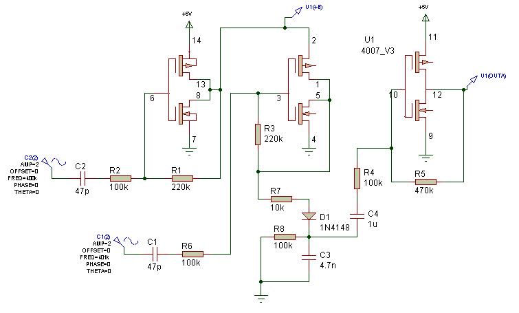
Nothing below is optimised in any way - just a quick proof of concept.. All the MOSFETS are part of the 4007, and pin numbers are shown (single 4007 used)


The most comprehensive data sheet for the 4007 I have found is this:

http://www.isi.edu/~vernier/EE327/cd4007_intersil_datasheet.pdf

Will perhaps post some waveforms here if anyones interested.

How it works:

First pair of MOSFETs (input on pin 6) act as an inverting amplifier, and amplifies / buffers the first oscillator (say the VFO) - the output of this effectively drives the +V supply pin (pin 2) of a 2nd inverting amplifier / buffer, whose input is the 2nd (say REF) oscillator (input on pin 3)

The output of this stage (pins 1 + 5) is the sum and difference of the two inputs - depending on the drive levels, the degree / depth of modulation (the superimposed difference on the carrier sum) will be determined - if this modulation is not excessive, either the +Ve or -Ve peaks of the waveform can be discriminated and will produce a reasonably true difference output..

R7 D1 C3 and R8 form a rectifier and filter which removes the HF sum and produces a difference waveform tracking the +Ve peaks of the heterodyned waveform. C4, R4, R5 and the last pair of MOSFETS form a inverting amplifier to amplify / buffer the audio.

The resistors on the output stage are absurdly high - should be more like 47k and 10k to reduce noise and C4 increased perhaps to 10u .. in fact the whole filter and audio side would need improvement,

Fred.

ADVICE / WARNING:

Dont build the above! - the transistors I used dont correctly model the 4007 - I have created new models from actual measurements and behaviour is quite different.. Fortunately, with the 4007 it is possible to get to individual MOSFET connections so my little Peak handheld analyser can give me (enough of) the charactaristics, and I have been able to replicate these with a subcircuit.. Now that I have these models I will re-design the mixer - my lab should be functional within a couple of weeks (slowly getting benches, power supply and equipment moved) and will be able to build things again - Then I will either verify or trash the crazy ideas I presented here.

Posted: 1/22/2014 5:13:21 AM
FredM

From: Eastleigh, Hampshire, U.K. ................................... Fred Mundell. ................................... Electronics Engineer. (Primarily Analogue) .. CV Synths 1974-1980 .. Theremin developer 2007 to present .. soon to be Developing / Trading as WaveCrafter.com . ...................................

Joined: 12/7/2007

Ok - I woke up an hour ago with some crazy ideas.. been thinking about them for an hour, and feel real frustrated because im almost sure they are stupid, but cannot explain why they are stupid!

These ideas relate to behaviour of molicules / atoms / electrons in a dielectric between two charged plates, and more particularly when the dielectric is gas or liquid - as in the case of theremin between antenna and ground / player.

My understanding of capacitance and the electrical field between plates is that the atoms of the dielectric (whether part of a complex molicule or elemental) are 'distorted' - Protons pulled towards the -Ve plate, Electrons pulled towards the +Ve plate. I accept that this "orbital" idea of atoms is an extremely crude analogy only, but for my purposes here its good enough..

"Adjacent" atoms line up, their electron orbitals being pulled towards the +ve plate...

Now the crazy idea.. Wouldnt this "pull" and "alignment" tend to restrict physical movement of the atom? If the dielectric is air, wouldnt the air between the plates (and particularly close to the plates - ie, antenna and grounded oblect) cause these atoms / molicules to be less mobile than those not within this field or further from the 'antennas' ? - If there was a flow of air blowing through this field area, and one was able to observe this flow, would one see any resistance due to capacitive charge?

This whole matter probably got processed in my subconcious because I have been trying to create an electronic "reed" for my capacitive wind instruments - I can process breath pressure / flow and drive a VCA / speaker fron this, but have been thinking that theres the natural power in breath capable of producing the sound without need for an amplifier, if I could just modulate this flow with the audio produced from the theremin circuits - so I have been playing with magnetic and piezo transducers trying to create this, all the time looking for some simpler way to electronically modulate air flow with minimum mechanical complexity..

I am now wondering if I could do it using  two plates and perhaps modulating these with a few kV (probably be blowing ozone out the other end.. ;-)

Fred.


Posted: 1/22/2014 9:45:48 PM
dewster

From: Northern NJ, USA

Joined: 2/17/2012

"The 4007UB still exists! I thought this part went extinct years ago, but its being made in RoHS DIL, and the TI version costs 17p.."  - FredM

I've never played with the 4007, and so didn't know the pairs were independent (i.e. of supply) which obviously makes it quite versatile.  I wonder if these, along with the DIP, will ever disappear?  Good way to learn on a breadboard, and some things are just too fundamental to chuck out.  Humans aren't shrinking either...

Interesting mixer circuit Fred!  You're making me want to stick my digital woes on the shelf for a while and build an analog Theremin or two!

"I can process breath pressure / flow and drive a VCA / speaker fron this, but have been thinking that theres the natural power in breath capable of producing the sound without need for an amplifier, if I could just modulate this flow with the audio produced from the theremin circuits - so I have been playing with magnetic and piezo transducers trying to create this, all the time looking for some simpler way to electronically modulate air flow with minimum mechanical complexity.."

Not trying to discourage you, and I realize you're looking for more of an acoustic valve, but there are only a few ways that I know of to modulate air under the control of electricity, and none of them are particularly efficient.  There's:

1. voicecoil & magnet & cone

2. piezo & cone (mostly HF)

3. DC motor & cone (for large stadium bass cabinets, I believe more efficient than #1)

4. HV and conductive "plasma" (I believe a production tweeter was made this way in the ~70's)

5. ultrasonic heterodyning (I believe requires high power to make air the non-linear "mixing" medium)

Gobs of people have spent gobs of time working on this due to the commercial applications, after all that it's kind of hard to believe #1 is what we generally end up picking.

Posted: 1/22/2014 10:06:00 PM
FredM

From: Eastleigh, Hampshire, U.K. ................................... Fred Mundell. ................................... Electronics Engineer. (Primarily Analogue) .. CV Synths 1974-1980 .. Theremin developer 2007 to present .. soon to be Developing / Trading as WaveCrafter.com . ...................................

Joined: 12/7/2007

" I wonder if these, along with the DIP, will ever disappear?  Good way to learn on a breadboard, and some things are just too fundamental to chuck out.  Humans aren't shrinking either..." - Dewster

I dont know -

Most new IC's arent appearing in DIL - and not just the big multi-pin parts.. Opamps, comparators, multipliers - 8 pin parts coming out only as SMD..

I strongly suspect that IC manufacturers will eventually go exclusively to SMD production, and that a seperate industry will be created for these parts mounted on DIL boards for hobbyists etc, at a much higher cost..

But I hope you are right! ;-)

Fred.

Posted: 1/22/2014 10:33:57 PM
FredM

From: Eastleigh, Hampshire, U.K. ................................... Fred Mundell. ................................... Electronics Engineer. (Primarily Analogue) .. CV Synths 1974-1980 .. Theremin developer 2007 to present .. soon to be Developing / Trading as WaveCrafter.com . ...................................

Joined: 12/7/2007


"Not trying to discourage you, and I realize you're looking for more of an acoustic valve, but there are only a few ways that I know of to modulate air under the control of electricity, and none of them are particularly efficient. " - Dewster

Oh, no discouragement recieved! ;-)

Route (1) has been my main route, even for the "valve" - My most functional "electronic reed" consists of two small magnetic transducers (the kind intended to turn any surface into a loudspeaker), and having these squeeze ("modulate") a piece of plastic tubing which I blow air through.. Its the modulation of this air (by any means) which im after.

But I will probably return to direct electronic amplification - its far cheaper and simpler... I was really exploring the valve idea primarily to reduce costs and complexity for a simple 'toy' EWI.. I might just end up using a solenoid driven with a square wave to implement this, rather than a shaped waveform - reeds are primarily on/off in nature anyway, and square shape (odd harmonics only) is quite natural for this kind of instrument.. The speed of the solenoid will impart other overtones which could be a problem, so I have some small fast pin solenoids for impact printers to try next - but I really need low cost, so am thinking of something simpler - like a flat piece of phosphor bronze acting a s spring and occluding the air exit, with an iron tip subjected to a modulating magnetic field..

I am a lot more curios about whether the idea that the electrical alignment in an air dielectric does actually impede air flow in any way - and if not, why not.. I realise that if it does, the forces will almost certainly be so tiny that they will be unusable for any practical application... My interest here is primarily in the science, and much less in the application...

But one thing I have pondered over for some years is whether there could be any way to "see" electrical / capacitive "fields" - I abandoned this thinking after going over all the possible mechanisms I could think of, and concluding there was no way with known science (or at least science known to me)..

If, however, there is a physical effect on air such as resistance to atomic / molecular mobility in a field, then there might be the possibility of sensing this and displaying it.. Optical distortion detectable with lazer for example....

I spent a week once in a farmhouse which had EHT pylons running through its (large) back garden - the sound from the wind through these pylons / cables was completely different to the sound from the wind through other similar uncharged structures.. I assumed this was due to leakage discharge between the (grounded) pylons and the cables.. But I think I was probably wrong... If this had been the case the sound would (?) have been continuous even when it wasnt windy... So I now wonder if this might have been "evidence" of restricted air mobility due to the strong electrical field..

?

Fred.

You must be logged in to post a reply. Please log in or register for a new account.