My New Year gift to TW: A new theremin circuit

Posted: 9/4/2020 12:09:58 AM
GuiFS

Joined: 8/30/2020

What I had in mind was getting a Rigol MSO5000 that I saw in an EEVBlog video (https://www.youtube.com/watch?v=P5faiEUXbGg&ab_channel=EEVblog — really good channel BTW, recommend for anyone interested in electronics), but the Hantek recommended by Thierry is very interesting too.

I found the problem with the circuit. Turns out the problem was noise injected by the power supply of the theremin circuit, I changed it to a classic transformer and rectifier PS and the noise was gone (trial and error, changing all the components, a lot of trouble for such a simple problem.). Anyway, thanks for the help and the scope suggestions.

Posted: 12/9/2020 4:54:06 PM
paludonho

Joined: 12/9/2020

Hi, if anyone could help me, I would be really apreciate.

I am trying to simulate the project on proteus, but it is not working. 

(for the antenna, I used an capacitor)

I will post the image here of the circuit.

Posted: 12/10/2020 2:04:58 PM
Thierry

From: Colmar, France

Joined: 12/31/2007

So what? The circuit is know working well in practice, why care about ambiguous simulations, especially if these contain major errors like the wrong FET types?

Posted: 12/10/2020 3:38:32 PM
pitts8rh

From: Minnesota USA

Joined: 11/27/2015

Welcome to TW paludoho!    That's Thierry's circuit, but stick around because others might help if he won't.  Simulation of theremins can be tricky, but once you get a decent model for the antenna circuits you can learn a lot. 

Our member Dewster has a ton of experience simulating and he can probably help you.  I'm sorry your first encounter here was like that, but please give the forum a chance.

Posted: 12/10/2020 5:12:40 PM
dewster

From: Northern NJ, USA

Joined: 2/17/2012

paludonho, you might want to start by simulating a single oscillator. 

Sometimes they need an initial condition (very small voltage applied somewhere, like at the antenna) to get going in simulation.  Sometimes it just takes a while for numerical "noise" to get it oscillating, have you tried looking way out in time?

Once oscillating, they often don't stabilize until after some significant time, I usually delay simulation data capture until after the oscillation amplitude is stable.

Posted: 12/10/2020 8:07:21 PM
Thierry

From: Colmar, France

Joined: 12/31/2007

In ever case, it’s highly recommended to start with the correct FET type. The 2N5434 is not a drop-in replacement for the required 2N5484!

Then, I second Dewster: one starts with one single oscillator. When this has proven to work, add the second one. And finally the active mixer stage. That’s also how I proceeded when I designed the circuit. It’s just that I built everything on breadboard. Often, the simulator models are too optimistic, real world components have tolerances and parameter straying (especially FETs), so one can’t really rely on them. Designing stable RF oscillators requires an experience (and some intuition) which no simulator has. A simulator won’t tell you how the pitch field feels to the player. Same for the mixer stage: the simulator will show you a waveform, but it won’t tell how it sounds. 

That’s why I consider simulations as almost useless in theremin design. 

Posted: 12/10/2020 8:24:37 PM
dewster

From: Northern NJ, USA

Joined: 2/17/2012

"That’s why I consider simulations as almost useless in theremin design."  - Thierry

YMMV, but sims have been extremely useful to me in my Theremin oscillator explorations.  Checking out a new topology is pretty painless (actually kinda fun) and if the sim oscillates there's a good chance it will work in real life.  It's much easier examining and adjusting transistor currents and voltage swings and the like in simulation, so you're starting at a better place on the bench.  It can also be quite educational trying to get the sim waveforms to match the bench oscillator (or at least attempt to reasonably account for any differences).  So much insight to be gained via both sim and breadboard, they complement each other quite well IMO.

Posted: 12/11/2020 10:24:24 AM
pitts8rh

From: Minnesota USA

Joined: 11/27/2015

"Often, the simulator models are too optimistic, real world components have tolerances and parameter straying (especially FETs), so one can’t really rely on them. Designing stable RF oscillators requires an experience (and some intuition) which no simulator has." - Thierry

With all due respect Thierry, these statements indicate an old-school way of thinking and a complete lack of exposure to modern simulators and methods used in industry.  While some including you try to perpetuate the myth and mystique of theremin design, in the bigger scheme of things a theremin operating at a few hundred kHz is pretty low on the technological food chain.

I am in no way a theremin designer but after several decades in RF and microwave design I can say with absolute certainty that there is not a single aspect of a theremin circuit that can't ultimately be accurately modeled in software, including "tolerances and parameter straying" and all of the other hand-waving arguments that might be invoked to dismiss its use and diminish its potential importance. Of course the human interpretation of what the theremin sounds like to a particular listener can't be modeled, but there is no need to perpetuate the myth that engineers and musicians can never cross paths.

A new user has come here looking for help.  I suggest that if you can't or won't help there is no need to be rude as you were in your initial response; just get out of the way and let someone else respond. I'm pretty sure that the Proteus software that paludonho is using is up to the job of modeling your theremin circuit with some intelligent application of the models currently available in the software, and the last thing I would want to do is discourage someone from getting involved on this forum.


Posted: 12/12/2020 11:06:36 PM
Thierry

From: Colmar, France

Joined: 12/31/2007

I don’t see anything wrong in being old-school, the underlying technology of a theremin is old-school, too.

Had paludonho not only tried to simulate his circuit variant but also built it with real components, he would have seen that his simulation corresponds perfectly to reality since with the selected FETs, it simply can’t oscillate. The potentially 2x or 3x higher drain current leads to a bigger voltage drop across the source resistors which shifts the operating point closer to cutoff, where the amplification factor is logically smaller.

Although pitts8rh might be correct in saying that modern simulators could perfectly simulate every aspect of theremin design, I still doubt, though, that the circuit designer sitting in front of a screen will get a realistic impression of the feeling or sensing experience of a musician playing the instrument. 

And my my modest experience is that the time needed to set up a nearly perfect (under technical aspects) simulation is an order of magnitude bigger than just opening the drawer, grabbing the needed components and soldering these quickly together.

Posted: 12/13/2020 4:13:32 AM
dewster

From: Northern NJ, USA

Joined: 2/17/2012

"Had paludonho not only tried to simulate his circuit variant but also built it with real components, he would have seen that his simulation corresponds perfectly to reality since with the selected FETs, it simply can’t oscillate. The potentially 2x or 3x higher drain current leads to a bigger voltage drop across the source resistors which shifts the operating point closer to cutoff, where the amplification factor is logically smaller."  - Thierry

My Thierrymin LTspice sim [LINK] oscillates with the 2N5434:

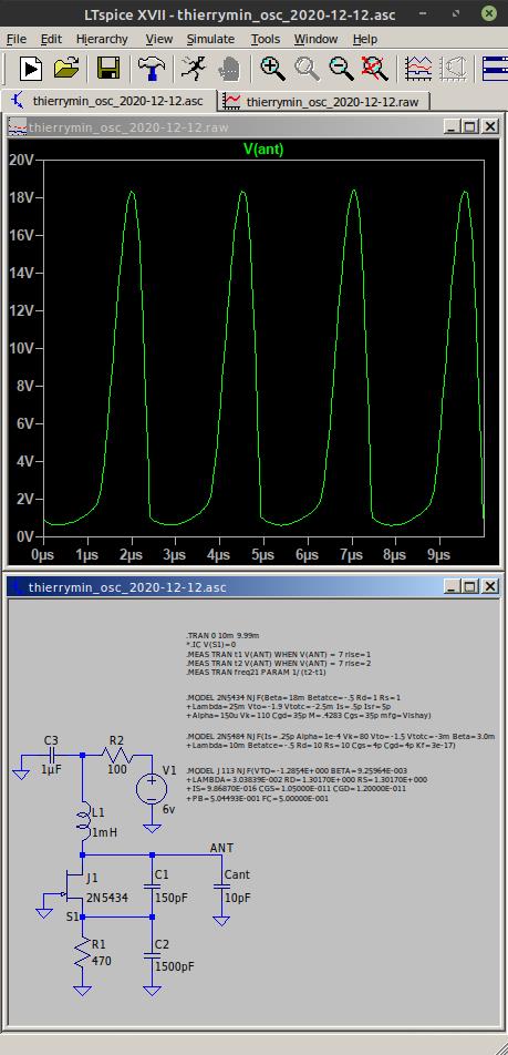
I think the 2N5434 is in the standard library, but I explicitly included it a .MODEL statement, and I got the params from here:

http://ltwiki.org/index.php?title=Standard.jft

If I had a 2N5434 around I'd maybe bench test it, but the sim voltage swing is rather low and non-sinusiodal, which seems typical of low supply voltage oscillators where the resonant coil is in series with the drain / collector (due to reverse conduction) and it doesn't have a digital use due to the sensitivity killing ~150pF in parallel with the antenna (which can be a useful thing for analog Theremins).

I don't think anyone would seriously argue that sims are the be all and end all to electronic design.  But they can be a very effective means to managing design complexity that our poor brains weren't developed to handle.  I mean, 90% of science is modeling in one form or another, whether it be via formulas, waveforms, FEA, Smith charts, etc.  If you're like Bob Pease and have reached the point where sims do you no good for smaller circuits, well good on you, but most of us benefit from them, and don't see them as impediments to understanding, or some kind of a crutch that weakens the mind.  Quite the opposite.  Not an argument from authority, but I've spent a couple of decades doing digital design and I literally couldn't survive without sims.  Digital teams always have guys sitting around simulating and looking for bugs.  Even the simplest stuff can behave in crazy ways that you just can't predict up-front.  Visibility into the inner workings is critical, and you can't easily probe memory contents or transistor currents.  Models don't have to be perfect to give you insight into what's going on (one often actually prefers simplicity to high fidelity).

You must be logged in to post a reply. Please log in or register for a new account.