static electricity spark now etherwave is silent

Posted: 1/18/2014 8:38:41 PM
Bob Klips

From: Columbus Ohio

Joined: 1/17/2014

H Thierry (and Fred). Thanks!

Yes the Q7 base to volume loop is OK, = 28 v. 

Regarding the -2.1 v reading at the node of D1/R14/C12, I noticed that this voltage varies when the volume knob is turned, ranging from -1.7 v when the volume knob is turned max clockwise, and -2.6 v when the volume knob is maximum counter-clockwise. Bringing my hand as close as I does bring the voltage difference down, to -1 v, not quite the 0.3 you suggested. Incidentally (this might be related to that), I have had a sense all along (in the few weeks I've had this, that the voltage "action" isn't quite as responsive as it seems to be on the instructional video (Thomas Grillo) I've been watching, and expected to do maybe have to do some internal adjustment. (Little did I know...) 

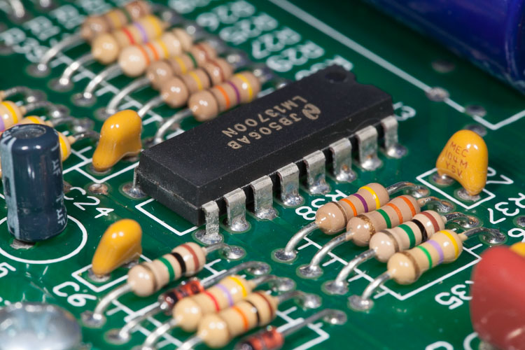
The fact that the voltage does vary, albeit not quite so much as expected, points to the LM13700 according to the logic set forth, for which I am very grateful! I'll look for that. I didn't see one of those at Radio Shack. I hope it isn't too hard to solder that 16-pinned monster. Or unsolder it. 

Is this the right track? 

Much appreciated!


Bob 


The first question: Your single resistance values (2 x 8R and 1 x 12R) are basically ok. But is everything interconnected? Check the overall resistance from the base of Q7 to the volume loop: Do you have a reading of about 30 Ohms?

The second question: are these -2.1V constant, even if you put your hand very, very close to the volume loop, but without touching it?
- If the voltage goes down to near -0.3V, that means that the volume oscillator is working and you'll have to replace the LM13700.
- If the voltage remains constantly at -2.1V, that means that the volume oscillator is not working and you'll have to replace Q6 and Q7 together.

Posted: 1/18/2014 10:08:17 PM
Thierry

From: Colmar, France

Joined: 12/31/2007

Most Etherwaves have the LM13700 in a socket, so that it can be replaced without soldering. They knew why...

I'm quite sure that it's the LM13700 (a cheap $3 part) which is defective, since you can vary the resonant current and thus the control voltage. With -1.7 to -2.6V at you should already have an audible signal at the output instead of -12V at PIN12 of this censored IC which corresponds to the totally muted state.

Posted: 1/18/2014 11:00:19 PM
FredM

From: Eastleigh, Hampshire, U.K. ................................... Fred Mundell. ................................... Electronics Engineer. (Primarily Analogue) .. CV Synths 1974-1980 .. Theremin developer 2007 to present .. soon to be Developing / Trading as WaveCrafter.com . ...................................

Joined: 12/7/2007

"They knew why..." " this censored IC " - Thierry.

LOL ;-)

I must object to your unfairly blaming a superb reliable IC for the failure of the EW designer to protect it from possible out-of-spec conditions! The LM13700 is now one of the very few low cost OTA's one can get, if not the only one... We dont want to lose it! - If it became unavailable one would probably need to construct OTA's from expensive matched transistor arrays like the THATS parts  (good arrays are as hard to find as other OTA's). 

As for "they knew why" well, it makes sense to socket components where applicable, even if one isnt abusing them! ... But given the choice between spending the money on a socket, or spending it on ESD protection, I would have chosen the latter.. For their cost, fitting both is the only wise route.

Fred.

*It should be noted that theremins are at ESD risk even if they are not powered! - It the theremin is connected to ground through ANY route (wiring to amplifier etc) thn the antennas are just as suseptable to ESD and damage can occur, whether turned on or not, whether the power supply is connected or not.

Just did a purely theoretical look at the volume circuit - The primary and lowest Z path for ESD that I could see was: L10->L9->L8->D1->C12->R17->GND.

Also C12 and L7 ->Q7:B then to +12V via Q7 Vbc, and to GND via Q7 be and R16.. Q6 is at risk via Q7e->Q6 Vbe ->R15->GND and also to a (much) lesser extent via Vec->L14->L11->+12V.

Then via R14, (dont think of this as a 1M resistor - with ESD its voltage will be grossly exceeded) to U3b, C27, R35, R37, D5 and C28 .. All of these components could have seen voltages well in excess of their specifications.

I would rate, purely from the schematic and not accounting for layout issues (which might alter everything) the components most at risk in the following order: those marked * are ones most likely to have sustained critical damage, others are likely to have sustained less critical damage

D1*, C12*, Q7*, C15,R17, Q6*,R15,C14, R14*,U3*,R35,C27,R37,D5*,R16,

I might replace these also.. Q8*,C16,R19,R20,C17,C18,R21,R22,R18,R40

The inductors L10 to L7 could have flashed, but IMO it is unlikely that non-recoverable failure would occur, and would be unlikely to replace these..

There are other possible paths, but I think the above covers the most likely damage routes BASED ON THE SCHEMATIC - I would certainly replace all these components if the theremin was mine to repair.. total parts cost well less than £5, and less than 15 minutes to do the replacement - I wouldnt even bother testing to find out which components had failed..

------------------

PLEASE NOTE - I am in no way trying to out-do Thierry here! Hands on, practical repair expierience is many times more valuable when it comes to matters like ESD than any theoretical "breakdown"! .. I am just exploring the theoretical which happens to confirm Thierrys first and subsequent suggestions! - but even if my analysis had turned out completely different, Thierry's would have been the one to listen to!

------------------

Added >> Quick look at pitch antenna ESD paths..

Primary routes: Antenna -> L1 to L4 -> C2 ->D4 and Antenna -> L1 to L4 -> Q1C

I would guess the following components are most at risk, in the following order: [enclosed] I would rate at equal risk..

[Q1*,C2,D4*,R2],[R23,U3*],[C1,C3,R3,Q2*,R1],[C6,Q3*]

-----------------

Looking at adding protection - A discharge tube between each antenna and ground is the first thing I would add, then on the volume circuit a transorb across C27 as well, and I would replace D1 with a better diode having high reverse voltage - perhaps one of the MUR family.

On the pitch side I would also add a transorb between Q1:C and ground. The capacitance of the transorb is insignificant at Q1:C and across C27. Alternatively, instead of transorbs, two fast diodes to the supply rails to clamp these points to rail voltages.

I would NOT fit transorbs or diodes without having a discharge tube on the antennas, as whilst these would protect the electronics, they would probably increase risk of damage to the inductors from ESD if discharge tubes were not fitted.. Discharge tubes are, IMO, Essential.

Posted: 1/19/2014 1:01:11 AM
Bob Klips

From: Columbus Ohio

Joined: 1/17/2014

Thanks tons! I ordered the LM13700. Mine doesn't seem to have a socket, however. Perhaps this is an early model? Should I add a socket...maybe that would lessen the possibility of heat or mechanical damage to the IC while soldering? 

LM13700

In the meantime, I'm playing the Theremin without volume control, which I was pretty much doing anyway. 

Thanks, 

Bob 


Most Etherwaves have the LM13700 in a socket, so that it can be replaced without soldering. They knew why...

I'm quite sure that it's the LM13700 (a cheap $3 part) which is defective, since you can vary the resonant current and thus the control voltage. With -1.7 to -2.6V at you should already have an audible signal at the output instead of -12V at PIN12 of this censored IC which corresponds to the totally muted state.

Posted: 1/19/2014 1:36:19 PM
dewster

From: Northern NJ, USA

Joined: 2/17/2012

"Should I add a socket...maybe that would lessen the possibility of heat or mechanical damage to the IC while soldering?"  - Bob Klips

Unsoldering and resoldering tend to beat up the PWB.  I would add a socket, the machined types are the best (14 pin below, you need a 16 pin):

To remove the old IC, I would use a diagonal cutter to snip the legs off the IC package, and then desolder them one at a time.  You might also want to buy a solder sucker, and perhaps some desoldering braid, which can really help when removing solder.

Posted: 1/20/2014 6:06:29 AM
FredM

From: Eastleigh, Hampshire, U.K. ................................... Fred Mundell. ................................... Electronics Engineer. (Primarily Analogue) .. CV Synths 1974-1980 .. Theremin developer 2007 to present .. soon to be Developing / Trading as WaveCrafter.com . ...................................

Joined: 12/7/2007

"To remove the old IC, I would use a diagonal cutter to snip the legs off the IC package, and then desolder them one at a time. " - Dewster

I have never really got on with the above method, but some people swear by it.. I think I was cutting the legs too close to the PCB.. I now do this method occasionally, particularly if the holes in the PCB are tight.. I found that cutting the legs at the top of the IC so that I could grab each leg with a crock clip and pull it while melting the solder did work well for one horrible multi-layer board I was mangling with my usual method.

Fred.

A RANT NOW FOLLOWS:

I do REALLY hate de-soldering IC's ! - And I fought hard with every employer to insist that good quality sockets were fitted.. One of the things I hate most about SMD is the lack of sockets on IC's.. The ability to simply unplug an IC and do tests on a board, makes debugging almost enjoyable - But some horrible flat square thing on the board with its >50 pins so close together you cant probe them - Nah - No fun !!!!!!

And this awful lead free solder - its like toothpaste when hot.. FFS!! - They still put sheets of lead on roofs with no problem, one of those is more lead than I have melted (or even caused to be melted in products I designed that got manufactured) in my life! - Dry joints? You cannot (or I certainly cant) tell a dry joint with this new solder - they all look bloody dry!

Yeah - Electronics is a lot less fun.. But at least we now have simulation so we can pretend to be making things even if we cant see real parts 'cause they are too small, and coudnt solder the bloody things even if we could see them, cause the solder is crap!


Posted: 1/22/2014 3:39:52 AM
Bob Klips

From: Columbus Ohio

Joined: 1/17/2014

Nice rant! I think I'm going to try, and probably skip the socket install (solder the IC in directly) when the IC comes, because I don't have a socket and they seem hard to find, am in a hurry, don't want to incur more cost, and hopefully won't need to replace the darn thing ever again. That's interesting about the lead-free solder. I have some leftover Pb solder that I will try to use sparingly I guess. 

Incidentally, right after the static spark zapped my Moog EWS I wrote to them inquiring about it, and yesterday I received this reply (below). Friendly and informative, and encouraging me to attempt the repair myself. And I'm sure you agree with the characterization of the role of the diode as a protective one? 

Hi Bob,

 Yes, that diode is designed to provide protection to the main circuit board, so when it breaks it did it's job. Static electricity can actually pack quite a voltage punch and due to the design of the theremin it is quite vulnerable to static discharge as a chunk of the circuit is just hanging out there.


It is this design that makes the theremin so responsive to gestures. I do highly suggest trying to remain cognizant of the risk, and discharge yourself before touching the antennae on the theremin, avoid shuffling your feet or heavy carpet, especially during the dry winter months.


The part that you will need is a 1N4148 diode. If you possess decent soldering skills you can easily replace this part yourself, or if you prefer you can request an RMA(repair authorization) and send it over to my shop for repair. Unfortunately, our minimum bench fee is $50 for out of warranty products, plus the shipping costs.

Posted: 1/22/2014 4:26:59 AM
Touchless

From: Tucson, AZ USA

Joined: 2/26/2011

Bob use a socket. Get it at Radio Shack and they still carry the good solder. For you to solder direct at this point "again" will completely trash your EtherWave if you get the Oh Shit shock again.

How do they say it, live and learn.

The Yellow Pages

1761 W Lane Ave, Columbus, OH 43221       (614) 486-5964
  • Cross Streets: Between Brandon Rd and Northwest Blvd

T

Posted: 1/22/2014 6:29:26 AM
Thierry

From: Colmar, France

Joined: 12/31/2007

I'm shocked to read about Moog Music's 50$ minimum bench fee... It seems that there is no more theremin idealism at all in that company, 8 1/2 years after Bob's passing away.

"What??? In the hotel??? For 50$???"


Posted: 1/22/2014 1:00:35 PM
dewster

From: Northern NJ, USA

Joined: 2/17/2012

PLEASE BUY A SOCKET!!!  (PM me, I will mail you one if necessary)

------------------------------

Yes, that diode is designed to provide protection to the main circuit board, so when it breaks it did it's job.

If the diode is sacrificial why don't they socket it, or put it on a header, or otherwise make it easier to replace?  I don't see similar protection for the pitch side?

Static electricity can actually pack quite a voltage punch and due to the design of the theremin it is quite vulnerable to static discharge as a chunk of the circuit is just hanging out there.

They seem to be saying their design isn't the best.  Or perhaps they are trying to implicate all Theremins here?

It is this design that makes the theremin so responsive to gestures.

It's a bug and a feature!  I don't believe one precludes the other, i.e. that you can't have both good sensitivity and good protection against ESD events.

I do highly suggest trying to remain cognizant of the risk, and discharge yourself before touching the antennae on the theremin, avoid shuffling your feet or heavy carpet, especially during the dry winter months.

But ultimately it's your fault for being a big dopey bag of water and static!  And it's winter and stuff!  Now pony up that $50+fees+postage!

You must be logged in to post a reply. Please log in or register for a new account.