On this page:
http://www.thereminworld.com/Forums/T/28530/antenna-tuning?Page=3
Thierry explains the relationship between the oscillator LC (tank) and the antenna series LC.. Its one of the most difficult aspects to grasp, and Thierry has explained it better than anyone else!
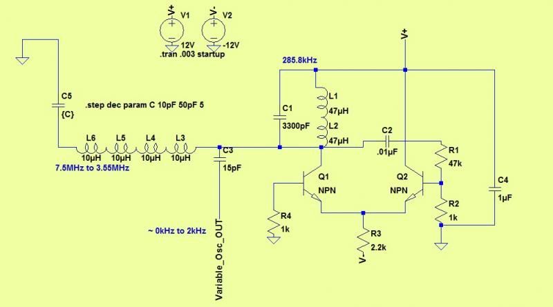
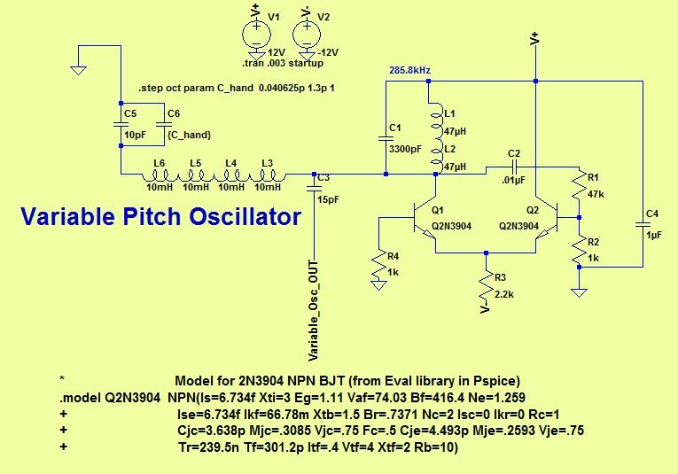
Simulation.. IMO, forget it! - This part of the circuit is almost impossible to simulate correctly - Or to put it another way - only if you set up the initial conditions absolutely correctly to place the oscillator operating point in the right place before you run the simulation, and have C5 set for a small change about the correct operating point (LC) will you get any usable results.. And then you need to convert C5 into a realistic table of distance <-> capacitance (accounting for background / unchanging capacitance) in order to do any useful plots..
Unless the players hand is really close to the antenna, one can expect change of about 2pF over the entire theremin playing range - and this change is not linear - a few hundred femto Farads change when you get further than about the mid point (say 30cm) from the antenna.. So no, 40pF is what you may get if you get 1mm from the antenna or thereabouts - not the kind of capacitance seen in normal playing.. One is looking at perhaps 10pF to 15pF antenna capacitance (I dont know the EW specifics)
*numbers given may be miles out - all sorts of factors come into play...
* Antennas are not "antennas" - they are merely capacitance sensors / plates - there is no "tuning" in the RF sense - the larger the antenna, the greater its capacitive coupling to grounded objects an the greater its sensitivity to the player.. The balance is to make its area large enough to provide sufficient change in capacitance to give adiquate pitch variation when being played, but small enough that background capacitive coupling doesnt 'swamp' the player coupling... In practice, its determined by the circuitry so that it provides, in combination with the circuitry, the correct frequency (and deviation) chosen by the designer - theres no magic number..
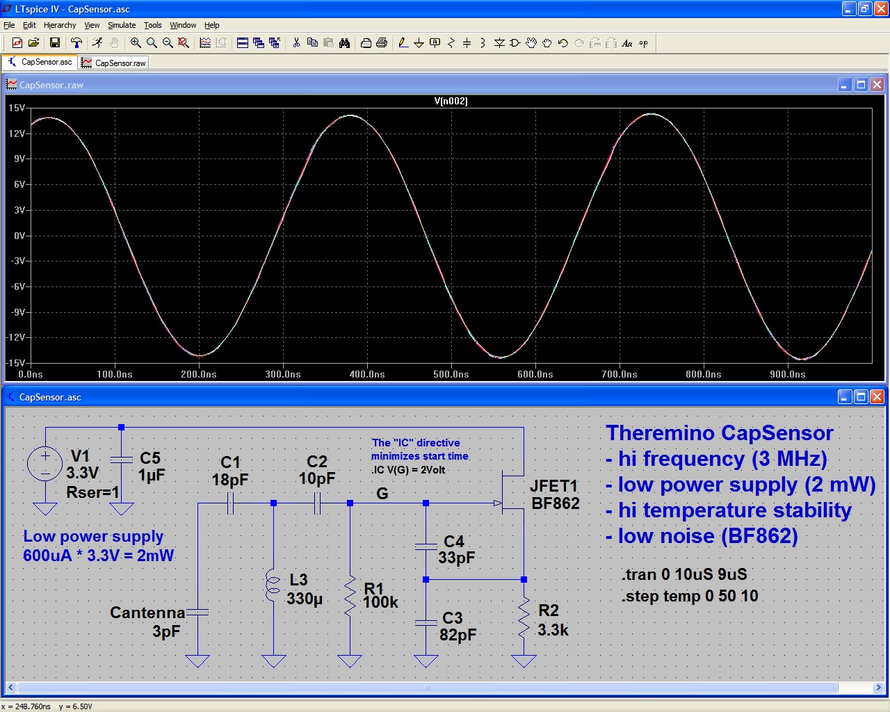
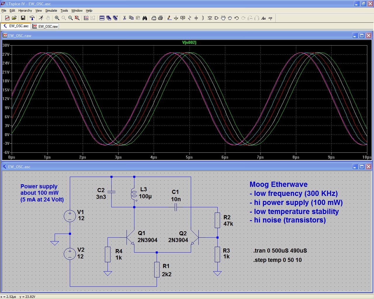
Oh - Just noticed the frequencies on your schematic! (7.5MHz to 3.55MHz) - Not sure whats going on with that simulation.. and BTW, which simulator is it? Looks a bit like LT Spice, but not quite...
Fred.