Let's Design and Build a (simple) Analog Theremin!

Posted: 12/1/2014 10:45:47 PM
dewster

From: Northern NJ, USA

Joined: 2/17/2012

"The c8 (4186Hz) can easily be played at 1cm of the pitch antenna on the tVox with three fingers stretched towards the antenna as I wrote above while I'll get an e7 (2637Hz) with the same hand shape at the same distance on the Henk. Thus I can't see from where you pull a two octave difference?"  - Thierry

I'm just going by the numbers you provided (plus some padding to reach the operating point).  Small changes in stray capacitance, or that trimmer on the Henk, could easily move things around an octave.  Right at the antenna where things go really non-linear might not be the best place to judge pitch placement?  I'm looking at mid-field response of the sim.  On the low end coupling can blow things out of the water as well (I assume no coupling).

"Sorry, but you are wrong."

I probably am and need to do some experiments along these lines.  I have tested three different lengths and the results of these tests are incorporated in the sim calculations.

Posted: 12/2/2014 12:33:19 AM
dewster

From: Northern NJ, USA

Joined: 2/17/2012

Breadboarding

I was curious how much capacitance there was between adjacent rows on my plastic breadboard.  In the past I've seen small yet often alarming differences between breadboarded vs PCB circuits, mostly with harmonics and switching.

Between adjacent rows I measure 2.02pF with the breadboard flat on my chipboard workbench.  Lifting it ~1cm this drops to 1.75pF.  This can be a lot of capacitance for RF circuits!

Lately I've been spreading the legs of transistors so they span 5 rows, with a "dead" row between each leg that goes unused.  This configuration reads 0.84pF with the breadboard flat on my chipboard workbench, and 0.61pF when the breadboard is lifted ~1cm in the air.  Not perfect, but a big improvement.

Posted: 12/2/2014 7:29:13 AM
Thierry

From: Colmar, France

Joined: 12/31/2007

That's why I never build RF circuits on breadboard. When prototyping, I use a kind of Veroboard but with small round copper dots instead of the usual stripes. 

Posted: 12/2/2014 4:06:24 PM
ILYA

From: Theremin Motherland

Joined: 11/13/2005

"I believe I've seen a large improvement using counter-wound air coils for L1 | L2 (i.e. reception / reduction of magnetic field interference)." 
 - dewster

I can be wrong (because I have not yet accurately analyzed the different variants of coil configuration), but a combination of two identical coils placed in parallel (and properly connected, a la coils in guitar humbucker) may work better. 

Reason: because of mutual inductance, the less total turns (and total wire length) will be required, so we'll get a higher SRF value (or lower "self capacitance").


Posted: 12/3/2014 5:30:00 PM
dewster

From: Northern NJ, USA

Joined: 2/17/2012

ILYA, it's true that two separate windings require a bit more (~25%) wire due to the intentional lack of coupling between them.  This extra wire likely lowers the Q somewhat (although air core Q is generally sky high when compared to ferrite core due I believe to the absence of magnetization losses).  And the undesired influence of magnetic fields on coils separated by some distance is likely stronger than that on coils that are more physically co-located due to gradients and such.  But I believe two windings in parallel will always give you less total inductance than the smallest inductance winding alone.

Say we have two equal windings L1 = L2 = 250uH and the coupling between them is good at k=0.9.  Then (from "Transformers & Induction Machines" by M.V.Bakshi U.A.Bakshi @ Google books):

The mutual inductance is then: M = k * sqrt( L1 * L2 ) = 0.9 * 250uH = 225uH.

Series aiding: L = L1 + L2 + M = 250uH + 250uH + 225uH = 725uH

Parallel aiding: L = (L1 * L2 - M^2) / (L1 + L2 - 2M) = 11875(uH^2) / 50uH = 237.5uH

Self-capacitance to a first order can be approximated via the distance between the ends of the windings - the series opposing with minimal coupling gives really low self-capacitance because this distance is maximized.

I haven't entirely thought it through, but I don't believe there is a way to do series aiding with concentric air coils (i.e. one layer on top of another with enough spacing to minimize capacitance between them) and also buck hum.  The same mechanism that gives you mutual constructive coupling will also couple external magnetic fields to both coils constructively.

Single layer air-core coils are fairly loosely coupled (particularly so when the wound length is greater than the diameter) so separating this into two counter-wound coils doesn't change the total value a whole lot.

Posted: 12/4/2014 5:15:08 PM
ILYA

From: Theremin Motherland

Joined: 11/13/2005

"But I believe two windings in parallel will always give you less total inductance than the smallest inductance winding alone. "

dewster,
I said "placed in parallel", not "connected in parallel". Certainly, the coils are connected in series so the case "L = L1 + L2 + M" is to be.

Just my case    "L=L1+L2+M"    vs     your  "L=L1+L2-M".

"Self-capacitance to a first order can be approximated via the distance between the ends of the windings" -- dewster

You surprise me, it's you who gave a link to Knight' paper?
95% of electronic people sincerely believe that the self-capacitance is due to the capacitance between  
turns. Are you on that side?


Posted: 12/4/2014 8:55:05 PM
dewster

From: Northern NJ, USA

Joined: 2/17/2012

I said "placed in parallel", not "connected in parallel"  - ILYA

Oops, my mistake.  Have you come up with a way to do this?

"You surprise me, it's you who gave a link to Knight' paper?
95% of electronic people sincerely believe that the self-capacitance is due to the capacitance between  
turns. Are you on that side?"

Not inter-winding capacitance, but between the end windings - which is apparently something of a canard, but gives serviceable low-ball estimates (according to Knight).

Posted: 12/14/2014 8:38:59 PM
dewster

From: Northern NJ, USA

Joined: 2/17/2012

REAL Antenna Data (and the implications thereof)

I've spent more time revisiting the pitch antenna geometry issue.  I tried a finite element analysis package (Quickfield) to help clarify things, but the student version didn't have enough resolution to even do even the simplest problems with any accuracy, and the geometry editor was too cryptic and weak.  Ran across LCnetgen yesterday which converts shapes into Spice models but didn't try it out (supposedly won't compile on Win machines).  My efforts to break the problem down into direct, fringe, and other fields haven't been very fruitful.

I've come to the conclusion that the search for a mathematical formula that approximates the mutual capacitance between hand and antenna is extremely difficult, fraught with controversy, and rather a waste of time.  So I decided to gather data for a variety of antenna geometries, stick this in a spreadsheet, work backwards to mutual capacitance, and then use this directly with analog and digital Theremin circuits:

http://www.mediafire.com/download/8qzfo3529j831if/Analog_Digital_2014-12-13.xls

The data isn't very high resolution (too few distance points) and the curves are somewhat lumpy even though I blend three trial runs for each antenna (this tends to reduce random error but doesn't help systematic error).  I'm still mulling it over, but:

1. For simple LC heterodyning analog Theremins it seems that longer antennas give better linearity, and thinner antennas give lower relative sensitivity - both of which are likely advantageous.

2. For simple LC heterodyning digital Theremins with offset period measurement, it seems a plate gives the most linear response with the highest heterodyning frequency, and also gives the most absolute sensitivity - both of which are definitely advantageous (and livio strikes again!).

3. For all antenna geometries, the mutual capacitance is very strongly correlated to 1/distance, and I believe this is why period measurement (1/frequency) yields such excellent linearity:

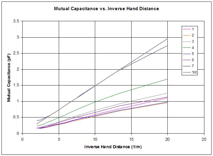
The above is a plot of mutual capacitance vs. inverse hand distance for all 7 antennae I gathered data for.  Other than absolute sensitivity differences due roughly to antenna surface area, some pooping out near the antenna (on the right here) is a bit more pronounced for longer antennae (which one might predict due to simple geometry), and rather abrupt pooping out as the hand reaches the body (on the left here), the mutual capacitance response of all antennae are remarkably similar and almost entirely characterizable via 1/d (e.g. the 7th antenna - a plate - is aligned above with 0.148/d).

Posted: 1/15/2015 9:15:18 PM
dewster

From: Northern NJ, USA

Joined: 2/17/2012

Cascode Vackar

Here's an interesting cascode variant of the Vackar oscillator I thought of a while ago and finally got around to polishing / simulating / benching today:

Q1 senses the oscillations across the capacitive divider Ctank & C2, and yanks on the emitter of Q2 via current rather than voltage.  The voltage at the base of Q2 remains fairly fixed due to C3, and this gives us the inverting cascode arrangement where Q2 is operating common base.  The Q1 & Q2 combo is high speed because the base-to-collector Miller capacitances are not magnified via the voltage gain (the base voltage of Q1 wiggles but it's collector doesn't, and vice-versa for Q2).  This is one way (perhaps the only way?) to construct a high speed inverter using bipolar transistors.

Simulation draws a fairly constant ~1.5mA which is neat.  On the bench I'm seeing a ~1.4MHz ~3V p-p sine-ish wave at the buffered output of Q3; and somewhere around 30Vp-p at the antenna, which one would expect for Vcc * C1 / (Cant || Ctank).  Any small signal / switching transistors seem to work well for Q1/2/3.  Seems pretty stable.  This is one oscillator that benches pretty much the way it sims.

LTSpice: http://www.mediafire.com/download/3957x07375gm10a/vackar_cascode_2015-01-15.asc

Posted: 1/17/2015 7:37:52 PM
dewster

From: Northern NJ, USA

Joined: 2/17/2012

Colpitts PNP

An interesting oscillator that uses a PNP BJT rather than an N channel FET:

Draws an almost constant ~0.3mA including the output buffer!  ~1.5MHz, ~25Vp-p at the antenna, 2.5Vp-p out.  Antenna voltage swing doesn't seem to be super influenced by antenna loading, which is nice.  Pretty stable on the bench.

LTSpice: http://www.mediafire.com/download/0qzy5bzzk926a1a/colpitts_pnp_2015-01-17.asc

You must be logged in to post a reply. Please log in or register for a new account.