Caglayan Tiny Theremin Build - pitch antenna issue

Posted: 8/31/2015 9:30:03 PM
oldtemecula

From: 60 Miles North of San Diego, CA

Joined: 10/1/2014

I am not familiar with this Hartley Oscillator configuration but my initial approach would be as above. I am open for suggestions because Google will pick this image up and we do not want to lead our grand-kids astray. We don't need another Glasgow design out there even though it is a beautiful place.

Christopher

The roll-over (-'

Posted: 9/1/2015 2:17:06 PM
xoadc

From: Moncton, New Brunswick, Canada

Joined: 4/24/2015

Wow!  Thanks for all the great feedback folks! 

I disappeared this weekend, and drove to visit a couple of friends who work in electronics in neighbooring towns to help me trouble shoot in person.... have not quite achieved perfection, but we made progress and discoveries!  Here is the update and replies to your feedback!

Dewster:   I would have started on a breadboard (to date most of my experience has been either on breadboards or direct wire to wire  projects with no board)... however, at several points in the Thierrymin thread people said not to use breadboards or stripped vero board because the strips would create interference... so I assumed breadboard was out of the question... In hindsight... I should have set it up that way anyway!  Next time.


Senior Falcon:  Yes, when I sweep through the variable capacitor I get a full range... however, there is some crackling noise at some points... and there are two points along the sweep that give good clean sound... so the variable cap sweeps through a range of pitches smoothly from low to high with a bit of noise, but at two points (one low and one high) the sound becomes very clear.


Dewster: YES! antenna to coil.   Just reading your comment now, but on the weekend, when I met with Rob, one of the things we tried was connecting the antenna to the tap of the coil in the VPO, and it worked!  Albeit backwards... low pitch was closest to the antenna, high pitch was further away... then it suddenly stopped.  More details about that below when I summarize what we tried and what happened.

I like the terminal strip suggestion too... I tried to buy some from a local electronics repair shop... but they had none... I'm sadly going to give up on trying to buy the electronic components locally and start ordering online. :-(


Christopher:  Rob also suggested putting some metal in the coils... When we dipped a nail in and out of the VPO coil, we got surprisingly clean sound, passing through the full range of pitch... low to high and high to low... very clean and clear... like what happened with adjusting the variable cap, but with no noise (at that point we had removed the variable cap and replaced it with a small 100pf cap.  It was really cool... but the antenna still didn't work... however, I might later on rebuild this circuit with the express intention of playing it by dipping a nail in and out of a coil... because that is also pretty cool... surprise discovery.

and AM radio, YES!  I'm not quite entirely clear on what you were suggesting I do... however, at one point in our trouble shooting, the amp that the circuit was plugged into started picking up radio... I can't remember what we did to the circuit when that happened, but when we undid it, the radio stopped.

and YES! I would love to invite you all over for a BBQ!  But I think we all live pretty far apart... however, I'm travelling down the east coast this fall and would gladly buy a beer or a coffee for any of you who are on my route! :-)


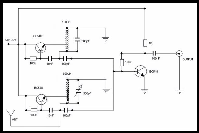
Senior Falcon:  yes, that's right... I'm just trying to make this circuit work... if Caglayan can make it work, I should be able to as well.  As long as that schematic actually reflects what he built....


Christopher:  You are adding to my homework!  But it's good... So, now I will try building that one too... Here is my order now:  1. Caglayan (keep trying to get it to work!)... 2. Thierrymin (build it)... 3. Hartley Oscilator Simple Theremin (suggested by Christopher just now... build that one too)... 4. PAiA Theremax (build it)... 5. Etherwave Plus (assemble it... the PCBs are sitting on my work bench... but it was so expensive that I don't want to solder any of those connections until I've built these other ones... I want to make sure that my soldering skills are up to snuff before I touch those puppies)


Finally, here is the update on what I tried and discovered over the weekend of trouble shooting with Gavin out in Sainte-Antoine and with Rob in Saint John (both of whom are experienced electronic instrument builders and musicians... and very very generous souls who offered to help me out in person *** I should add that I squeezed meetings with them into a very tight schedule... so I only had 1 hour with each of them... in that short time, there is a chance I may have misunderstood or wound up misquoting certain aspects of their advice... so if there are errors in our findings, they are likely mine):


1. Tools, circuit, and soldering: Gavin inspected my soldering and my circuit and my tools that I was working with.  I learned some great tips!  I was running my iron too hot.  My solder was a bit too thick for the job (working with 1.2mm when 0.6 or 0.8 would do). A few of my joints had lifted from the board. And I should try to keep my circuit components tighter and closer together (less spread out... which would mean shorter wires as Christopher suggested earlier in this thread).  He also suggested I solder terminals to my board, instead of the transistors, so that if I need or want to try flipping them... it's easier, and I'll be less likely to burn them out when attaching.

2. Transistors:  Upon inspecting the circuit we discovered that there was a problem with my transistors.  I had bought them from a local electronics repair shop, they do sell components, but they often seem annoyed to go looking for them in the boxes out back... there were no data sheets, and the guy at the shop wrote the pin order on a piece of paper for me... as CBE... so I installed them that way... when checking the voltage, something seemed off, so we looked up their data sheets online... the pin order is actually EBC.  So, it appears that they were in backwards. (tansistors were BC547 and not BC548 like the schematic - the shop told me they were equivalents)

So, I snipped off the transistors, and put 3 new ones in... the proper direction, and resoldered them to the now growing solder blobs... and... it sounded better!  However, the transistor in the FPO got very hot, and the one in the mixer got warm... the one in the VPO didn't get hot.

So.... I'm not sure what that's about... I'll double check the pin order online again... and who knows... maybe the schematic had one or two of them drawn in backwards?  I'm taking the schematic as gospel... but maybe there are some errors in it...


3. Coils - Rob suggested we put nails in the coils.  That made the sound louder, but the antenna still didn't work.  However, moving a nail in and out of the VPO coil offered control and the ability to sweep through pitches.  I shot a video of that to share with you all... but somehow the video didn't record... witchcraft!


4. Variable Capacitor:  adjusting this, sweeps through the range but there is some noise, and the antenna offers no control.  So, we tried two other variable caps.  same thing.  we swapped out the cap for a small 100pf cap and that worked better - cleaner sound, and that was what allowed the nail in the coil to offer control.


5. antenna:  after switching the transistors, and replacing the variable cap with a 100pf cap.. we tried connecting the antenna to the tap on the VPO coil... and ta-da!  the antenna offered control... about 12 inches around the antenna worked... but it was backwards... close to the antenna gave a low sound and further away was higher pitch. 


6.  sudden silence!  but then, in our glee at getting the antenna to work... it all of a sudden stopped... no sound at all... silence... and that was the moment that the transistor in the FPO was super hot!  almost burnt Rob's hand... and we checked the other two... and the transistor in the mixer was warm, and the one in the VPO was cool.  Perhaps it was the quick and dirty job attaching the new transistor... or maybe that one should have stayed in its original position.


So... next steps: I'll check my transistors again... flipping them yielded results... but that FPO one shouldn't have gotten hot... I wonder if it was wrong on the schematic.  I will try flipping that one around.  I'm also using BC547 (because that's all the local shop had, and they said it was equivalent to the BC548 on the schematic)... I'll order some BC548s.


Parts:  I'm sadly going to give up on getting them from the local repair shop here in town... it is always an ordeal when I go in there, while they look for the parts... (they're a repair shop... not a supplier after all)...  they often give me "equivalents" instead of exactly what I'm looking for... and they are way too expensive... so, today I will place an order online... and get these parts again... and try building from scratch, as I think my solder blob are making repairs a bit unweildy.

and there you have it... progress... but not perfection... it gave me hope though... so I'm going to keep trying to make this one work!


Posted: 9/1/2015 3:22:50 PM
oldtemecula

From: 60 Miles North of San Diego, CA

Joined: 10/1/2014

A Lady of many words who said: 

6.  sudden silence!  but then, in our glee at getting the antenna to work... it all of a sudden stopped... no sound at all... silence... and that was the moment that the transistor in the FPO was super hot!  

My schematic above is a redraw of yours, look closely. Added are Pot-1 and R5, these will limit the transistor overheating you are experiencing which is thermal run-away or even a dead short through the coil as nothing limits the current flow.

The variable cap is too difficult to tune, as you have found there are other methods to tune, including my Pot-1 configuration.

A theremin as a byproduct puts out a Radio Wave that you can detect as a blank spot on your analog AM Radio within 12" of the theremin, digital radios do not work. Even better you need to use this bargain frequency counter so you know where both of your oscillators are tuned so you can match them in frequency.

Christopher

Posted: 9/1/2015 3:39:01 PM
xoadc

From: Moncton, New Brunswick, Canada

Joined: 4/24/2015

:-) many words indeed... I was trying to be thorough...the devil is in the details. :-)


I see what you mean about the extra parts in the schematic!  I get it now!  thanks!!!


for testing... beyond a radio, I also have an oscilloscope that a friend gave me... this can also be useful I presume?


In terms of the oscillators, I see that oscillators (FPO and VPO) are key elements of the theremin circuit... someone referred to this diagram as a sort of "colpitts oscillator"... I have been reading about oscillator circuits online and watching videos about them... but am still trying to wrap my head around exactly what the oscillator circuits are doing (i.e. what are the electrons doing and how are they being manipulated) in this circuit... what is actually physically happening here?... I know that's probably really basic, so if you don't want to make this thread too heavy with that... feel free to share any links to things that I could read that might help clarify the science and physicality of what is happening on the most basic level here. :-)  thanks!


Posted: 9/1/2015 6:39:59 PM
dewster

From: Northern NJ, USA

Joined: 2/17/2012

"I would have started on a breadboard (to date most of my experience has been either on breadboards or direct wire to wire  projects with no board)... however, at several points in the Thierrymin thread people said not to use breadboards or stripped vero board because the strips would create interference... so I assumed breadboard was out of the question... In hindsight... I should have set it up that way anyway!  Next time."  -- xoadc

Plastic breadboards have rather high capacitance between adjacent strips, but this can be minimized by using every other strip.  I do this all the time and it works quite well.

I also want to point out that when you tune a Theremin via variable capacitance from antenna to ground, you run into something I've cryptically dubbed "the invariant".  Due to multiplying effects of tuning and sensitivity, the variable cap will be quite a bit more sensitive than you might naively expect. 

"In terms of the oscillators, I see that oscillators (FPO and VPO) are key elements of the theremin circuit... someone referred to this diagram as a sort of "colpitts oscillator"... I have been reading about oscillator circuits online and watching videos about them... but am still trying to wrap my head around exactly what the oscillator circuits are doing (i.e. what are the electrons doing and how are they being manipulated) in this circuit... what is actually physically happening here?... I know that's probably really basic, so if you don't want to make this thread too heavy with that... feel free to share any links to things that I could read that might help clarify the science and physicality of what is happening on the most basic level here. :-)"  -- xoadc

My method of figuring out what the heck is going on with oscillators has been to simulate various circuits in LTSpice, which you can download for free from Linear Technologies.  The key is how the feedback sustains oscillation.  Some topologies employ the transistor as an inverting amplifier and rely on a phase inversion between two ends of the LC tank.  Others directly stimulate the LC tank and use no inversion.  There is usually a split capacitor or a tapped coil to separate sense from drive.  It can take a lot of investigation to really understand things, but there isn't any substitute IMO.  Reading papers on-line may actually slow the process down because designers tend to get bogged down the minutia associated with specific topologies.  One unusual goal for quality Theremin oscillators is a high-ish voltage swing at the antenna, which you can accomplish in various ways - surprisingly it doesn't necessarily require tapped coils or step-up transformer windings.

Posted: 9/2/2015 3:22:03 AM
senior_falcon

Joined: 10/23/2014

 My schematic above is a redraw of yours, look closely. Added are Pot-1 and R5, these will limit the transistor overheating you are experiencing which is thermal run-away on even a dead short through the coil as nothing limits the current flow.

Christopher

-----------------

Good catch Christopher; there really is nothing there to limit the current flowing through the transistor.  We are still left with the question of why the theremin in the video works and xoadc's theremin doesn't. I wonder if it would work if you reduced the voltage from 9 volts down to 3 volts.  That would reduce both the current  and the wattage to be dissipated by a lot and it might be a quick and easy fix to get it working without modification.

Amanda, I would guess you would have no problem with the BC547 transistors you used or even the 2N3904's that Chris shows.  Be sure to check which pins are emitter, base and collector. The 547 is not the same as the 3904!

Posted: 9/2/2015 3:51:02 AM
dewster

From: Northern NJ, USA

Joined: 2/17/2012

That was a good catch RS!  The original schematic seems to be relying on weak base bias current to limit the collector / emitter current.  Which is poor design because beta (current gain) is a very ill-defined BJT parameter, and emitter resistors are needed to prevent thermal runaway.  

For instance, the 100k base resistor has 9V / 100k or roughly 0.1mA flowing through it.  If the beta is 100 then the transistor could be conducting 10mA which seems excessive to me, particularly with the lack of emitter degeneration.

There's an ocean of crap out there that noobs have to wade through.

Posted: 10/15/2015 7:10:41 PM
xoadc

From: Moncton, New Brunswick, Canada

Joined: 4/24/2015

I FOUND IT!  This is what I was trying to understand... how does an LC tank circuit or oscillator work?  Why is it there and what are the electrons doing?

This little video offers a great explanation and animation!  Very simple, he talks quite slowly, but I get it now!
The animation and explanation starts at 1:40   https://www.youtube.com/watch?v=fQ4yRVEzXQA
there's a faster version at 4:30


So, I haven't gotten the Caglayan circuit working... but I understand it now.


Last night I assembled a Thierrymin... it makes no sound though... Thierry was super helpful this morning and walked me through testing every part and connection with my multimeter... according to the multimeter it's good... but I'm not getting any sound... I had to leave my work station before trying anything else on that one after testing it... but my guess is that either A.) the connection to my antenna is inadequate, or B.) the cap trimmer I haven't found the right point... who knows... I'll try a few more things tonight.


I'm on a residency right now for artists working with radio, and am screening my film about radio towers on the weekend.  When they heard that I was working with theremins, they asked if I could teach a theremin building workshop... but as you all know, I'm no expert and haven't made one work yet... so, instead, I proposed a "theremin building bee"... like a sewing bee... but with soldering!  a soldering bee... this Saturday morning, 5 people are coming out, and I'm providing all the components for each person to build a Thierrymin... and the schematics, and lots of diagrams and articles I have as handouts... and we're going to work together as a group on building our Thierrymin circuits... and learn from each other... hopefully someone else's will work better than mine! :-)

Posted: 10/15/2015 7:16:34 PM
xoadc

From: Moncton, New Brunswick, Canada

Joined: 4/24/2015

OH!  I just thought of something... in terms of both my difficulties with the Thierrymin and the Caglayan here...


the studio I'm working in right now is right beneath a radio station... It's a residency for artists working with radio... they have 3 stations broadcasting... and it's on 10 acres of land, and all over the property there are other art installations with radio transmitters... there is almost no cell phone reception here... for that, I have to hike up the side of the mountain.... so I'm surrounded by computers and amplifiers and radio transmitters... that might very well be affecting my results right now.

Posted: 10/15/2015 8:38:51 PM
dewster

From: Northern NJ, USA

Joined: 2/17/2012

Watched the video, I think he is describing things in a black / white sense rather than the real shades of gray.  The inductor and capacitor in an LC tank don't take turns, they are constantly operating on each other.

One can think about LC for a long time before getting an intuitive sense of what's going on.  For me, capacitance seems pretty easy, but inductors seem pretty weird.  Inductors are like springs in a way, you can quickly yank (change the voltage) on the other end of a grounded inductor easily, but then the current required to maintain the voltage increases over time.  Capacitors are the opposite, requiring lots of current initially for a quick change, dropping to zero over time.

I think the problem with your circuits is likely tuning, the range is really small over which it will work, so you need to have very fine control over it.

You must be logged in to post a reply. Please log in or register for a new account.