


dewster (hi, BTW!),
looking to the EW PCB design again and again, I wonder what the asshole launched such the placement of the volume/eq coils?
In terms of the EM immunity the chain must include the EVEN number of coils which are parallel (or axial like this =):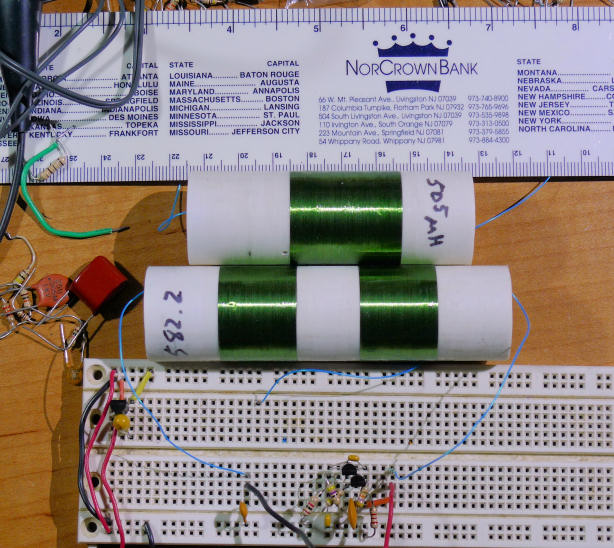 ), identical and counter-wound in pairs.
To overcame the problem of two versions of the same component ("right" and "left" wound inductances) the identical coils are oppositely connected in pairs.
Why is it so taken in EW?
The "Parasitic capacitance reduction" (allegedly!) is more preferable than "EM immunity"?
Parts clarification for Etherwave Theremin build
Posted: 9/10/2015 7:15:43 PM
Posted: 9/10/2015 9:19:32 PM

Why is it so taken in EW? The "Parasitic capacitance reduction" (allegedly!) is more preferable than "EM immunity"? -- ILYA
Hi! That's my feeling. Self-capacitance reduction is probably more central to operation, interference reduction not so much. Though I agree with you, the use of 3 coils and their orientation is strange. From my limited anecdotal experience, electrical field interference is probably worse than magnetic field interference, and coil count / orientation probably doesn't help you much there after it gets picked up by the antenna.
Posted: 9/11/2015 4:22:08 PM
IMHO the special arrangement for self-capacitance reducing is a myth.
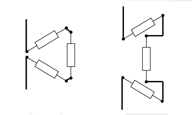
If coils are placed at distance more than a diameter (the dimensions of EW PCB allow it), the coil orientation is irrelevant to "total self-capacitance".
Here are some results of my experiments as a proof: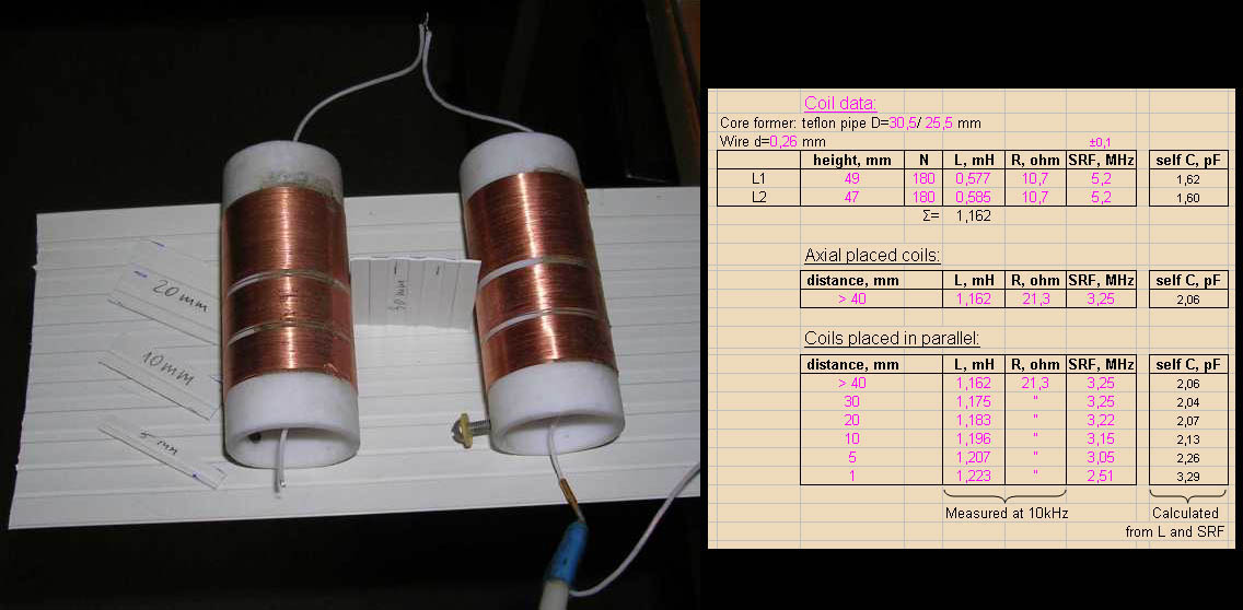
The total "self-capacitance" is the same (around 2 pF) as for axial placing, as for parallel case where the "hot" end of the chain is located opposite the "cold".
Similar paradoxical results are reported in D.Knight' paper.
Posted: 9/11/2015 6:14:50 PM
ILYA, I don't believe coil orientation has much if anything to do with self-capacitance. But due to the way series capacitance adds (1/[1/C + 1/C]), placing coils that have a certain self-capacitance in series can give you a lower overall self-capacitance than one big winding. Hence the multiple separated "donuts" on Bourns RF chokes.
Coil orientation is more for coil coupling and magnetic field interference reduction.
Do you agree? Or am I missing something? For the distance in the picture you show above, There s/b almost no magnetic coupling between the coils (from my experiences playing around with the Inca program).
Posted: 9/11/2015 8:12:23 PM
You dont believe, I dont believe, but Moog engineer does!
You mentioned the rule 1/[1/C + 1/C], but this rule is not work here (refer the table: 2 pF vs expected 1.6/2=0.8 pF)!
And yes, "there s/b almost no magnetic coupling between the coils" for the distance in the picture (1.175 mH@30mm vs 0.577+0.585=1.162 mH) .
Posted: 9/11/2015 9:41:03 PM
You mentioned the rule 1/[1/C + 1/C], but this rule is not work here (refer the table: 2 pF vs expected 1.6/2=0.8 pF)! -- ILYA
You're down to almost no C, so I'm not sure the measurements can be entirely trusted to be bulk C? I mean, the wires hanging off the ends of the coils have some C with free space (a 1.5 mm diameter wire 75 mm long is ~1pF). Are the coils sufficiently suspended above anything else that they might be capacitively interacting with? Not saying you're sloppy or anything, just that these kinds of measurements are so close to the noise they might need to be taken with a grain of salt, even if you are being very careful when taking them.
That said, it does seem your measurements can be used for comparison purposes, and it's very interesting that there is no clear benefit in keeping the hot and cold ends apart. I suppose there may a bit of superstition involved in the EW layout. Certainly if there is no obvious down-side to keeping the hot/cold ends separated, one can easily assume it is best (minimum risk) to do so.
Posted: 9/18/2015 10:33:58 PM

dewster and FredM are brilliant engineers and they think like engineers. But let's not forget that a theremin is a music instrument which is to be played by a musician.
A musician will not expose his instrument to extreme ambient temperature variations. He will bring it into his practice room or concert venue, let it acclimate for half an hour and then tune it, as a violinist would do, too. After a few minutes of playing he would check and perhaps slightly adjust the tuning, and that's all and ok.
You can't naturally prevent drift in theremin oscillators. But that is not forcibly a problem. Since the audio signal is generated through heterodyning, everything is about the frequency difference. Thus, the circuit designer has to make sure that both oscillators drift the same amount which is not difficult when using identical components for both oscillators. ---Thierry
Thierry, what you really think about identical oscillators in Etherwave? In the matter, it is not really identical, taking linearising coils into cosideration... and some capacitors and resistors are not identical... IMHO, Lev Koroliov in 2005 design (you know) has totally identical circuits, really...
Posted: 9/19/2015 7:04:08 PM
Thierry, what you really think about identical oscillators in Etherwave? In the matter, it is not really identical, taking linearising coils into cosideration... and some capacitors and resistors are not identical... - Alesandro
Good point, the linearizing inductor creates a very real resonance with the antenna / hand capacitance. Any non-identical factors between oscillators can contribute to drift, so one might expect the linearizing inductor to show up in the fixed oscillator as well. Cost is likely the main reason it doesn't. That, and the small capacitance it resonates with (<10pF) might make the fixed oscillator too sensitive to external capacitance.
You must be logged in to post a reply. Please log in or register for a new account.