Measuring Antenna Capacitance

Posted: 11/25/2016 6:07:02 PM
ILYA

From: Theremin Motherland

Joined: 11/13/2005

This is a continuation of this topic.

I started making a set of antennas with variable length. Each rod is assembled from multiple pieces according  1-2-4-8  code.
At the moment the sets of 3 and 7 mm segments are ready:

The 10 cm, 20 cm and 40 cm  segments (with the base 10 cm segment)  allow to vary the length of antenna in range 10 to 80 cm  with 10 cm increments.

 Segment junctions:

The Meter:

Posted: 11/25/2016 9:50:46 PM
DOMINIK

From: germany, kiel

Joined: 5/10/2007

Very good. Will it double as a playing robot? Seems to me like it could be inviting to feed the stepper motor with notes (while mirroring the results of course).

Posted: 11/26/2016 1:07:44 PM
dewster

From: Northern NJ, USA

Joined: 2/17/2012

ILYA, how do you get the "hand" positioned in the center of the various length antennas?

From all I know, having gone down a similar (less automated but more realistic) path, the results will be obvious from just a few experiments, and the fine antenna length adjustments won't be necessary to clearly see them.

Posted: 11/27/2016 7:57:23 AM
randy george

From: Los Angeles, California

Joined: 2/5/2006

Interesting project, ILYA.  After seeing this device, I was reminded back to an old thread. Maybe a good idea if everyone had a look at it again. A few of us were discussing linearity from the player's point of view.  The "infinite angular couplings" principle comes to mind when I see your device.  Check out FredM's diagram depicting couplings. There was also mention of approaching specific locations on the pitch antenna to achieve optimal linear pitch interaction.   I personally approach the center of the pitch antenna, but I know not everyone does this.   However for consistency in your testing, you should probably approach the vertical center of every "test antenna".

http://www.thereminworld.com/Forums/T/29078/linearity---players-point-of-view?Page=1

Posted: 11/27/2016 3:32:54 PM
dewster

From: Northern NJ, USA

Joined: 2/17/2012

I'm thinking perhaps the geometry of the experimental arm doesn't adequately reflect how most people actually play the pitch antenna.  The antenna is vertical but the experimental arm is rotating horizontally.

Standing at my prototype I tend to pivot my arm vertically at the elbow, and employ the upper arm and hand for larger movements:

Now, god knows how I'll actually play it when it starts making noise (!) but probably not horizontally (famous last words).

Again, not trying to discourage you ILYA or poop on your experiment, just thinking out loud about stuff (rather than coding!).  Your current arrangement does have the advantage of a clear distance measurement between the center of the antenna (in terms of cross sectional diameter) and the center of the plate - I was never quite sure what/now to measure in my own experiments (to be consistent I settled on the distance between the nearest hand point to nearest antenna point, and centered on the antenna length).

And as Randy points out in that thread, body C can have a lot of influence over linearity (particularly when there is the second resonance of an EQ coil).

Posted: 11/27/2016 5:29:16 PM
ILYA

From: Theremin Motherland

Joined: 11/13/2005

Dominik,
after all the measurements will be completed, I plan to turn my meter to "robotized assistant". Not sure I will need in second "arm" for volume control, but with replacing  CY8C27xxx to  CY8C29xxx family (which has the matrix 4x4 of digital blocks) I can easily add the second motor channel. The task I interested is not to use a method based on the note-to-position calibrating tables (nevertheless, I'll start with this), but a technique based on the feedback (correcting the current position of "arm" using the difference between measured and desired frequency).

"how do you get the "hand" positioned in the center of the various length antennas?" - dewster
"However for consistency in your testing, you should probably approach the vertical center" - randy george

I can't yet. Any ideas?
At first I would like to start with static capacitance measurements. Next week I will try to find the 12, 20 and may be 30...40 mm  pipes. Up to make them out of paper and aluminum scotch.

Randy, thanx for the link. The feeling that Fred is still with us. Will be read because seems I have missed this thread. 

Posted: 11/27/2016 6:29:19 PM
dewster

From: Northern NJ, USA

Joined: 2/17/2012

"I can't yet. Any ideas?" - ILYA

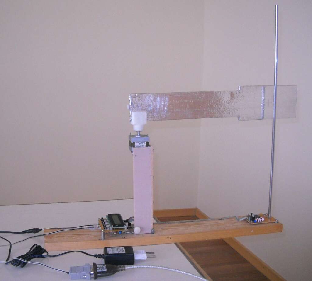
I did this by mounting the oscillator and antenna on a camera tripod, which has easily variable height:

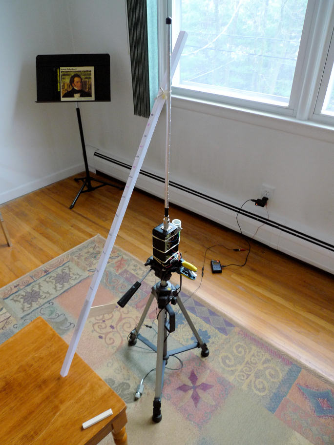
My plastic measuring stick (seen drooping onto the chair I sat in here during the measurement process) was affixed via plastic hardware (screw, cable clamp, and wire tie).  I first tried using a wooden stick but I noticed that it perturbed the oscillator when I brought it near the antenna, whereas this plastic stick didn't.

To accommodate a "loose" antenna location you could maybe have a step in the initial calibration process that would find the point at which the "hand" touches the antenna and calculate the distances based on that?

I must say, this was one of the most basic and definitive (in my mind) experiments I've ever done - I wish I'd done it much earlier in my Theremin investigations.  Using my real arm and real body, I don't think anyone can argue too vigorously that the setup and results have no basis in reality.  And following it up with rigorous simulation sealed the deal (in my own mind at least).  I think we perform these kinds of experiments mainly so that the numbers can guide us, rather than the mountain of (however well informed) conjecture in the field - numbers don't lie.

The area rug is long gone (student threw up on it, LOL :-)

[EDIT] Hey ILYA, can you move that stepper motor fast enough to measure latency / bandwidth?  If so this might be the best apparatus for quanitifying it in various Theremins. Even analog Theremins can have slow response times if they don't use the heterodyned result directly as audio.

Posted: 12/3/2016 2:03:18 PM
ILYA

From: Theremin Motherland

Joined: 11/13/2005

Ambient temperature 25.4 C, humidity 29% (31% after), pressure 98.3 kPa.
The Moon is in Capricorn.

Antenna static capacitances (w/o and with the ground plane 25x41 cm, which imitates a metal chassis):

The ground plane used:


Posted: 12/3/2016 2:10:04 PM
ILYA

From: Theremin Motherland

Joined: 11/13/2005

Some pics.


The Meter is located above the wooden floor at 80 cm. The free space around antenna is 1.5-2 meters at least.

The clamp is made from the plexiglas and thumbscrew:


Full set of antenna rods (3, 7, 12, and 20 mm diameter):


Instruments (barometer and psychrometer, vintage models) to monitor the environment:


Calibrating with the reference capacitor 49.75 pF (two of 100 pF in series):


The value 49.75 pF has been measured by the immittance meter (E7-8, certified) with accuracy of 0.1 %.
The pin over nut has a capacitance 0.0199 pF (was checked after the initial calibration). On the subsequent calibrations it was used as a "low point" reference capacitor.  

Posted: 12/3/2016 3:17:27 PM
ILYA

From: Theremin Motherland

Joined: 11/13/2005

"[EDIT] Hey ILYA, can you move that stepper motor fast enough to measure latency / bandwidth?" - dewster

And it is necessary? The latency is completely determined by the measurement time which I choose, is not?

You must be logged in to post a reply. Please log in or register for a new account.