


Hi, as I'm sure you're all well aware building theremins can be very hard, especially for a beginner like me! We found a guide online, ordered in the components and built it but no luck so far! I've attached the circuit we used and a picture of our circuitry, thing is we've double checked our signal and it seems to be very clear but the frequency is very low, only 50 hertz. Is this a major problem? What is going on? We tried attaching an antenna, but there is very little change in frequency, is this expected or a problem?
HELP WITH FIRST THEREMIN?!?!?!?
Posted: 2/2/2017 3:24:11 PM
Posted: 2/2/2017 3:26:57 PM
http://i.imgur.com/0LwTF6p.jpg
http://i.imgur.com/5xUcqWg.png
Forgot to attach the images lol, here they are.
Posted: 2/3/2017 12:04:16 AM

thereminotaur:
1. Put the breadboard on top of a small plastic box (3" high or more) to minimize capacitance.
2. The critical (oscillator) wires should be kept shorter than you have, though you are doing the right thing by routing them in the air rather than right next to the breadboard.
3. Don't space everything within a single oscillator out so much, try to keep the components close.
4. Space the oscillator transistor leads out so there is a blank row in between them to minimize capacitance (collector, space, base, space, emitter).
5. Check the power supply voltages at the breadboard rails. Check transistor voltages for proper biasing, for the NPNs the emitter should be 0.7V or so below the base, the collector above both. Get each oscillator up and going one at a time. The NPN is the actual oscillator, the FET is just a buffer and doesn't do anything but unload the oscillator / mixer connection.
6. The heterodyning point can be really tricky to hit if you only have coarse tuning.
7. Employ consistent color codes of the wires, particularly for power and ground.
8. Check actual resistor values with a DMM. Color bands can often be difficult to read (e.g. red or orange?).
9. You picked a fairly complex circuit to start off your journey: IMO tapped inductors are generally asking for trouble unless you know what you are doing, and there are much simpler mixers out there.
10. Good thing you have a scope! Try putting a 1pF cap in series with the probe when you're checking for oscillation so you don't kill it by loading things down with the raw scope probe. If the oscillation voltage is large you often don't have to physically connect the probe to anything, just place it near the antenna, to know if oscillation is happening. But that's after you have it up and running reliably.
Posted: 2/3/2017 10:32:46 AM
thank you so much Dewster my dude, we will implement all these tips and see what happens.
Posted: 2/3/2017 10:34:39 AM
do you have any suggestions for simpler circuits? we only started with this one because it was the clearest one we could find online
Posted: 2/3/2017 12:15:01 PM
Ok we did what you said, cut out a few wires, elevated it, didn't have time to colour code it though, here's our new circuit:
http://i.imgur.com/134vjsC.jpg
and here's what the scope read:
http://i.imgur.com/9fD9MfW.jpg
We are getting a frequency of only 50Hz, is this to be expected? We've built one the two oscillators that make up the pitch control so far and we're testing each one at the point where it would go to the mixer. The transistor pins gave a different voltage to what you said, emitter was 17v, base was 7v and collector was also 17v. All resistor values were correct.
Posted: 2/3/2017 8:28:09 PM
It's still fairly rats-nesty, but I've seen worse work.
I think the 50Hz you're seeing is simply mains hum? It's only some tens of mV in amplitude and noisy.
Seems like your emitter bias is going to the positive rail rather than to ground? Check the power supply voltages at the breadboard, you usually have to provide jumpers between all the busses you're using (no internal connection).
You might also confirm the transistor pinouts with the datasheet (staggered lead types are the mirror image of in-line lead types in terms of the flat on the package).
Check that your transistors aren't blown with a DMM in diode check mode: pull them from the board and look for forward voltage drop of 0.6V to 0.7V from base (+) to collector (-), and base (+) to emitter (-). The opposite polarity checks should look essentially open (infinite ohms).
Here is a NPN Colpitts with PNP buffer that works well for me, almost any small signal transistors should work, almost any coil should work, and the resistor values could be adjusted to work at higher voltages if you like:
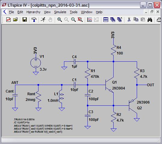
Cand and Rant aren't real components, they are standing in here for the antenna in simulation.
You must be logged in to post a reply. Please log in or register for a new account.