Tried to simutate phase shift based sensor.
Looks promising.
Phase shift detector output may produce PWM, which can be easy converted to analog level just by LP filter, and then measured by ADC.
Did someone used this approach in theremin?
Tried to simutate phase shift based sensor.
Looks promising.
Phase shift detector output may produce PWM, which can be easy converted to analog level just by LP filter, and then measured by ADC.
Did someone used this approach in theremin?
"Did someone used this approach in theremin?" - Vadim
I believe so. There was a new Theremin discussed here a while back that used two tubular antennas and a tiny control box - the Nano. The builder showed up and when I quizzed him about it he said it was analog and I understood the functioning to be this way. FredM tried this method and he didn't like it for the pitch side.
If you sampled the voltage fast enough you could use a software CIC filter to kill mains hum.
Tried it on breadboard.
Worked fine in LTSpice (resonance frequency for 1mH and 6pF is near 2MHz, up to 100V voltage swing on antenna). Nothing close in reality. But probably 2MHz is too high frequency for my coils. With smaller coils 470uH I see at least some change in oscillation amplitude on scope, and no big visible phase shift. But it's far from resonance.
Yeah, you need better coils. Ones with too much self capacitance / core loss will either perform poorly or completely fail at higher frequencies. When I first started down this path I had one coil in my junk box that worked and a bunch of others that didn't. Messing around with poor coils is a waste of time.
Looks like self resonance frequency in coils I tried to use was too low.
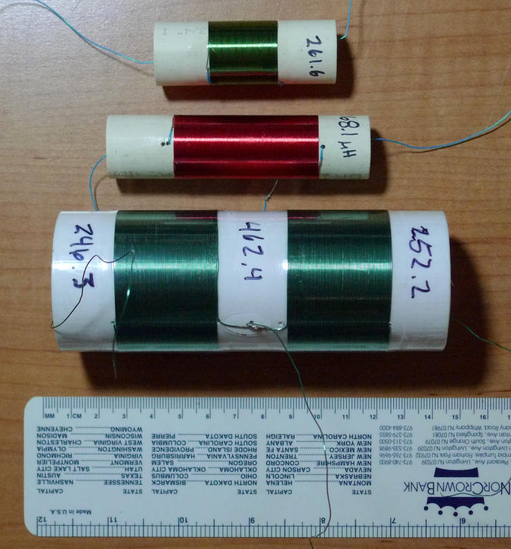
Winded DIY coil. 0.3mm wire, about 7 layers of coils. Air core. Serial resistance is 6.3 Ohm (comparing to 2.2 Ohm ferrite coil I used before), L is more than 1mH - when changed 1mH coil with my one, frequency changed from 941 to 623.
Not sure what is Q for this coil.
Winded one layer coil

D 32mm L 70mm, wire 0.3mm
According to COIL32, it should be ~560uH, Q = 280, self cap 1.3pF serial resistance 5.4 Ohm, self resonance ~ 3.7MHz.
Not yet tested.
My wood cabinet has 40mm internal height. If my coil has wood surface above and below at distance 3-4mm, will it affect inductor performance?
Strange observation: when I tried on breadboard oscillator without C in parallel with antenna (just L -> Antenna hanging in air) - I saw a kind of amplitude modulation. Will retest with better coil and tuned oscillator amp.
BTW, could you advise some better NPN transistors than 2N3904? Hfe I measured for my 3904s is in range 180-200.
"My wood cabinet has 40mm internal height. If my coil has wood surface above and below at distance 3-4mm, will it affect inductor performance?"
The wood cabinet being that close will increase C somewhat. If the distance is kept constant it probably won't matter too much.
I don't know of better NPN off the top of my head. Almost any small signal should work as RF oscillator. FETs are interesting also here, I've had pretty good luck with them.
You should get a cheap LC meter from eBay or similar. The LC200A is pretty nice (though don't trust it for accurate C change vs. temperature). The LC200A can read antenna intrinsic, which is pretty cool.
I've designed oscillator with maximum sensitivity (no caps parallel to antenna) in LTSpice.
According to model, voltage swing on antenna should be 120-160V.
For direct frequency measurement (after frequency divider, of course).

And then tried it on breadboard. ICs are 7HC393 for frequency divider (powered from separate 3.3V regulator).

I was surprised finding it working right after assembly. Frequency and amplitudes are as predicted by LTSpice.
Waveform on scope looks a bit different from LTSpice model.
Frequency is about 2460KHz (this means, antenna cap is 8-9pF). Frequency reacts on hand - changing pitch by about 7-10% (visible on scope), but it's visible when hand is near (10-15cm) from antenna.
Scope shows about 30-40V voltage swing on antenna, but probably it's just caused by scope probe capacity.
TODO: test stability by measuring frequency divider output using MCU. Will do it tomorrow.
"Frequency is about 2460KHz (this means, antenna cap is 8-9pF). Frequency reacts on hand - changing pitch by about 7-10% (visible on scope), but it's visible when hand is near (10-15cm) from antenna." - Vadim
Any reason you're going for this high of an operating frequency? Granted, this is in a pretty quiet spot in terms of other terrestrial transmitters. Lower frequencies require larger inductors, but they are easier to drive from a phase error standpoint, and are easier to measure. Though you could just use a digital divider (like you are doing).
"Scope shows about 30-40V voltage swing on antenna, but probably it's just caused by scope probe capacity."
I measure antenna swing through a 1pF cap and calculate the voltage drop due to 8pF scope probe C. (8pF + 1pF) / 1pf = 9x what you read on the scope.
You must be logged in to post a reply. Please log in or register for a new account.