Let's Design and Build a STM32 Theremin!

Posted: 11/25/2017 7:20:22 PM
gerd

Joined: 11/25/2017

Hey,

I'm thinking about building a theremin based on a STM32 microcontroller.

It should be a simple theremin with excellent sound quality. It must be cheap and easy to build.

I have an Open Theremin V3 and for me there is too much digital noise in the audio signal. It sounds like you can hear the frequency where the the volume and pitch values are sampled.

The idea is to use a STM32F407G-DISC1 . It's a 20$ board with an STM32 and an audio DAC with integrated class-D amplifier. There should be only the 2 oscillators for volume and pitch and a voltage regulator. So the external part is very simple, cheap (<5$) and could be build up without SMD components or PCB.

Basic points:

  • cheap (25€ without mechanical parts and pots)
  • easy to build
  • clear sound, less digital noise
  • lookup table for waveforms
  • support of waveforms with subharmonics
  • linearization of pitch, logarithmic correction of volume
  • fast auto-tune (<1sec)
  • no mixer
  • optional display for pitch

gerd

Posted: 11/25/2017 8:20:35 PM
dewster

From: Northern NJ, USA

Joined: 2/17/2012

Hi gerd,

Interesting comments re. the Open.Theremin.  I don't have direct experience with it, but I've looked at the schematic and code, and I believe you.  The operating point sampling rate is too low and insufficiently filtered IMO.  The processor itself is too wimpy.

I can't be too arsed to paw through the documents you point to, but it seems to be ~200MIPs with enough Flash & RAM.  The D/A is 12 bits?  If so, that's not enough for audio IMO.  My advice is to SPI or similar over to a 16 bit or more audio DAC.  I'm using an inexpensive SPDIF to analog audio converter box that sells for ~$10.  Using optical SPDIF here gives you a super low noise floor (you can stick a red LED directly inside the TOSLINK hole).

As for your other specs, I'd be happy to work with you on an inexpensive FPGA support chip that does what you want, other approaches are too involved and picky IMO.  The FPGA interface to the processor would look like a register set.  It wouldn't be a walk in the park, but it's the most direct route to a pro Theremin that I know of.

Do you have a decent scope?  You'll need one for Theremin work.

Posted: 11/26/2017 9:32:57 AM
gerd

Joined: 11/25/2017

>The operating point sampling rate is too low and insufficiently filtered IMO

Yes. With the STM32 and e.g. 400kHz oscillator frequency with 8 bit prescaler I would have every 50kHz/20µs a new pitch value to walk through the wavetable. So more or less the same frequency as the sampling frequency.

>but it seems to be ~200MIPs with enough Flash & RAM

And with FPU and DSP instructions. In a former project I've realized a PID controller in a 1µs task, using float point arithmetic.

>The D/A is 12 bits?  If so, that's not enough for audio IMO.  My advice is to SPI or similar over to a 16 bit or more audio DAC.

There is a CS43L22 audio DAC on-board. Stereo, 24bit, 96kHz. The micro itself has a 12bit DAC. I think it would be suitable for some debug purpose, e.g. I could map the antenna frequency on this DAC and could see if there is 50/60Hz noise to adapt some kind of notch filter.

Posted: 11/26/2017 5:04:23 PM
dewster

From: Northern NJ, USA

Joined: 2/17/2012

"Yes. With the STM32 and e.g. 400kHz oscillator frequency with 8 bit prescaler I would have every 50kHz/20µs a new pitch value to walk through the wavetable. So more or less the same frequency as the sampling frequency." - gerd

One thing to watch out for is a pitch value update that is near, but not exactly, the audio sampling (PCM) rate, which can cause sampling and alias problems.  This is why I run the oscillator update rate at a multiple of the PCM (~196MHz), then downsample and filter via second order CIC.  A high oscillator update rate means noise picked up by the antenna below 1/2 this rate won't alias into the pitch value (if properly filtered) and I can use a relatively low order filter to resample the update rate at the PCM rate.

"And with FPU and DSP instructions. In a former project I've realized a PID controller in a 1µs task, using float point arithmetic."

I'm sure you've got enough processor there to do Theremin C sensing and voice generation.  As I'm sure you know, the question is what additional hardware is necessary to sufficiently unburden the processor.  For the soft processor in my FPGA I use extra FPGA hardware to buffer and drive the LC oscillators, pitch display, LCD, encoders, SPDIF, SPI, UART, etc. leaving minor filtering tasks to the processor assembly code.  The 8 threads are almost entirely free to do linearization, offset, voice generation, UI, etc.

"There is a CS43L22 audio DAC on-board. Stereo, 24bit, 96kHz. The micro itself has a 12bit DAC. I think it would be suitable for some debug purpose, e.g. I could map the antenna frequency on this DAC and could see if there is 50/60Hz noise to adapt some kind of notch filter."

Ah, sorry, I should at least have caught that!  If the 12 bit A/D D/A work past 10MHz or so you could drive/sense the LC tank with them, but I don't think these do?  Beyond that I can't think of a use for them.

Custom hardware in an FPGA makes the most sense to me.  (I know I'm an FPGA guy so I tend to pull out that hammer for every nail I encounter, but in this case I'm pretty sure it's true.)  FPGAs have a hell of a learning curve, but there's absolutely nothing like having an ocean of configurable logic at your fingertips.  You could likely do what you need to do with a <$20 Cyclone demo board. I've already developed all the Theremin-based SystemVerilog code you would need for it.

Posted: 11/28/2017 7:06:08 PM
gerd

Joined: 11/25/2017


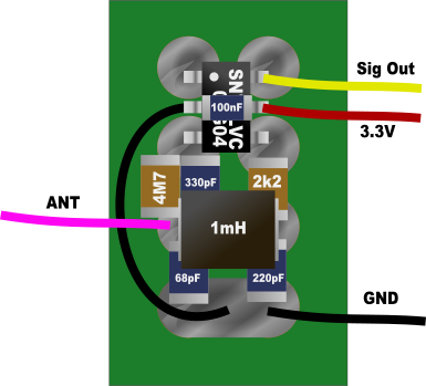
This is an idea how to build up the oscillator. It's a good old colpittsbased on the SN74LVC1GX04 and soldered on a standard breadboard. So no PCB would be necessary. SN74LVC1GX04 is SOT23-6, 100nF is 0603 and other resistors and capacitors are 0805. Inductor: NLFV32T-102K-EF

Posted: 11/28/2017 7:33:32 PM
dewster

From: Northern NJ, USA

Joined: 2/17/2012

Any oscillator that puts significant capacitance in parallel with the antenna will significantly reduce absolute sensitivity (change in F with change in hand C).  Low sensitivity means you will have a harder time measuring the signal (particularly digitally) and any instabilities (drift and noise) becomes magnified with low sensitivity.

Ferrite core inductors tend to be temperature sensitive, and many have low Q at resonance (particularly when resonating only with the antenna C).  You have to pick them very carefully.  This is why I use air core inductors, they have high Q and low temperature drift.  And this is why the Etherwave uses RF chokes and IF transformers.

If you have fine enough frequency control via processor PWM, you might try stimulating the LC tank directly with a square wave.

Posted: 12/3/2017 1:39:51 PM
gerd

Joined: 11/25/2017

Thank for the hints.

I will also try an air core inductor. The STM32 project should be more or less independent of the oscillator. The software should accept any oscillator at the input capture pin from 48kHz up to round about 1.5MHz.

Posted: 12/3/2017 1:40:18 PM
gerd

Joined: 11/25/2017

Last days I also thought about a fast implementation of a LED tuner on a STM32 controller (with floating point hardware). This was my idea:

  1. Calculating the frequency from the period value but with 16.3516Hz as numerator
  2. The result is a float value. The exponent is the octave.
  3. With the mantissa I go into a table with 1024 entries to get the tone, or better directly the 7-segment code for the display including the "#".

Here is the C-pseudo code:

float_frequency = 16.3551f / timer_period_value;

int_octave = (FLOAT_STRUCT)float_frequency.EXPONENT;

int_mantissa = (FLOAT_STRUCT)float_frequency.MANTISSA;

IO_PORT_WITH_7SEG_OCTAVE_DISPLAY = octave_2_7seg[octave]; // Table with 10 entries

IO_PORT_WITH_7SEG_TONE_DISPLAY = logarithmic_7seg_table[int_mantissa >> SCALE_TO_10BIT]; // Table with 1024 entries


So this should be done in round about 100ns .. 200ns


Posted: 12/3/2017 2:41:55 PM
dewster

From: Northern NJ, USA

Joined: 2/17/2012

I'm doing much the same thing using unsigned 32 bit ints.  If you get tricky you can do it without division.

The player needs to see sub-note information as well, and here I'm using pulse width modulation (PWM, the addition of a 180Hz sawtooth) to dither the note display number.

I don't think seeing note letters themselves is the most intuitive or useful display of pitch.

Posted: 12/16/2017 4:53:12 PM
gerd

Joined: 11/25/2017

Today I've published the project on github [tinnitus32]

Functionality today (Dec 16th 2017): Plays a sound with fix frequency from a wavetable. Reads timestamps of pitch oscillator input capture channel. I'm going to write the code for the basic Theremin functionality during the Xmas holidays.

It will be open source and I plan 2 version running the same software: One where you need only the STM32 Discovery board, 2 oscillators for pitch and volume and maybe 1 knob and 3 pots. And the 2nd one with more functionality and maybe a PCB.


You must be logged in to post a reply. Please log in or register for a new account.