Let's design and build cool (but expensive) FPGA based theremin

Posted: 6/19/2018 7:29:03 AM
Buggins

From: Porto, Portugal

Joined: 3/16/2017

I'm working on digital theremin project for more than one year.
First attempt was to use ARM MCU, but I switched to FPGA approach after I faced problems with low sensitivity of MCU based theremin sensor implementation.

    Project goals:
        Extreme sensitivity and fast response of theremin sensor
        Pitch and volume values updated for every sample (48 or 96KHz)
        Minimal soldering - use board with most of available features built in
        User friendly controls
            Big touchscreen
            Pots and/or encoders on front panel if necessary
        On-screen pitch preview - mixing of pitch preview to headphones signal is not necessary
        Form factor - near to etherwave

FPGA is required at least to build extra sensitive theremin sensor.
If there is FPGA anyway, we can implement synthesizer DSP in hardware as well.

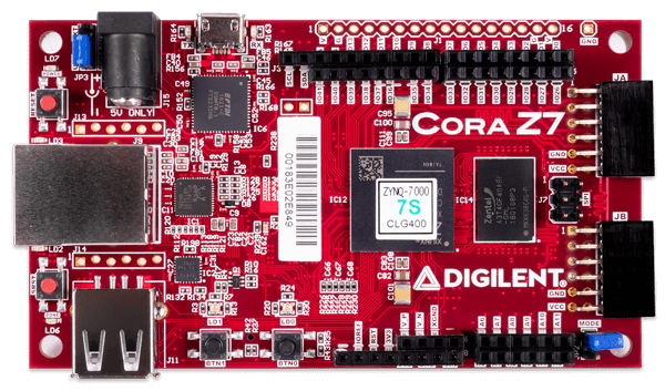
I've started with Arty S7-50 Xilinx Spartan 7 based board.
But once I saw number of resources occupied by soft CPU + DDR controller, and a lot of soldering required to connect audio boards and screen,
I decided to choose different hardware.

Current hardware I'm using
    Zybo Z7-10 - $200
        https://store.digilentinc.com/zybo-z7-zynq-7000-arm-fpga-soc-development-board/
    Waveshare 7" 1024x600 LCD with HDMI interface and touch screen via USB HID -- $60
        https://www.waveshare.com/7inch-hdmi-lcd-c.htm
       
So, overall hardware cost is expected to be $300-$350
   
Zybo Z7-10 has on board audio in/out, so no addition audio board purchasing nor soldering is required.
Screen is connected via HDMI and USB connectors - no soldering.

Unlike Dewster's project which uses strange PLL based frequency measurement,
I've decided to use direct measure of oscillator frequency period.

This approach requires oscillator with maximal max/min frequency change on hand movement.
(Minimal capacity in LC oscillator parallel with antenna).
Oscillator is simple single NPN transistor, 74HC invertor to form square form output signal, and ESD protection diodes.
Oscillator frequency decreases by ~5% while hand approaches to antenna.
Two oscillator PCBs are the only part which requires soldering skills.
Outputs of oscillators are 3.3V digital signals which should be somewhere in range 250KHz .. 4MHz.
Oscillator outputs are just connected to two PMOD connector pins.

Parts which are done:


Theremin sensor controller is implemented in FPGA part.
    Interface:
        2 digital inputs - for pitch and volume antenna oscillator signals
        2 digital outputs with generated test signals (for testing purposes may be routed to inputs)
        AXI4 Lite slave interface to access controller registers and lookup tables from PS(ARM MCU)
        Volume and pitch period direct outputs - may be used by synthesizer
        Clocking inputs
       
    ISERDES is used as input for signal period measurement cirquit (1.2GHz effective precision)
    4-8 signal period measurement blocks are used to measure the same signal shifted by different delay in delay lines - for oversampling
        (adds 2-3 bits)
    Both raising-raising and falling-falling edge intervals are measured (adds one more bit to period value)
    Total number of signal period bits is near 13-16 depending on oscillator frequency. Precision is equivalent to period measure with ~10GHz base clock.
    Measured value is passed to averaging filter with flexible coefficient - goal is to average values for ~ 1 sample interval (48/96KHz).
    After filter, we have more meaningful bits of oscillator frequency value.
    Once per sample (48000 times per second) controller performs processing cycle.
        Measured oscillator signal interval is passed to scaler with MinPeriod and MaxPeriod parameters - setting for near and far hand positions.
        Scaler scales input period values from MinPeriod..MaxPeriod interval to 0x000000..0xffffff (out of range values are clamped).
        1024x32bit lookup table based interpolator converts scaled period value to linear hand distance (or directly to volume control value - for volume).
        For pitch value, there are two more stages:
          1024x32bit lookup table based interpolator converts hand distance to note value (fixed point MIDI note number) - applies note range; pitch correction can be applied using this table
          1024x32bit lookup table based interpolator converts note value to note base frequency phase increment (alternative point of pitch correction)
    Register values and lookup tables are available to CPU via AXI bus interface.
    Control registers:
        Pitch and volume
            Measured period value before averaging filter
            Measured period value after averaging filter
            Averaging filter coefficient
            Scaler MIN and MAX values to specify scaling range
            Value after scaler
            Value after linearization lookup table
            Value after note lookup table (for pitch only)
            Value after phase increment lookup table (for pitch only)
        2 test signal generator periods and enable/disable flags
        Lookup tables content may be modified from PS(MCU) - each is 1024x32bit
            Linearization table for Pitch
            Linearization table for Volume
            Distance to Note table for Pitch
            Note to Phase Increment for Pitch
    TODOs:
        Calculate change detection (e.g. differential) - e.g. to control some synthesizer parameters on volume (left hand) attack/decay.
       
HDMI framebuffer controller is implemented in FPGA part.
    Fixed 1024x600 resolution with 8 or 16 bits per pixel (RGB 322 or 565 pixel format).
    Framebuffer address is set via memory mapped register (avaliable from PS/MCU via AXI4 Lite Slave interface).
    End of frame (VSYNC) interrupt output
    Built in DMA access implementation
    Total resources used are several times less than in standard controller from example
   
GUI library for framebuffer - development in progress
    Drawing of primitives and text is implemented
    Emulator to test GUI code under windows
   
Audio output
    Built in I2S interface for audio output (24bit, 48 or 96KHz) available from FPGA
    Work on audio I/O and mixer IP is not started yet

Synthesizer
    Work is not started
    As first implementation I'm going to try additive synthesis (SIN lookup table based sine wave generators).
        Set of harmonic amplitudes define instrument
        Amplitudes and phases may be controlled from by oscillators to get nice sound color.
   
   
Current activity: support of touch screen
    USB Host driver is required to get touch screen HID reports
    There is no out of box implementation of standalone USB Host
    Trying to port tinyusb library to Zynq
   
   
FPGA resources available after Sensor Controller and HDMI implementation: about 90% - may be used for DSP and audio out.

PS(CPU) resources:
    2 ARM cores with floating point support, 533MHz
    1Gb DDR RAM
    Core 1: common control and GUI
    Core 2: DSP (10000 clock cycles per sample at 48KHz) - may be used for some advanced instrument implementations


Posted: 6/19/2018 10:26:36 AM
Thierry

From: Colmar, France

Joined: 12/31/2007

Coming from the "Theremin Motherland", you most probably know the inventor's original design and patent in which heterodyning is a big, important, and characteristic part of the music instrument. Without heterodyning, by directly measuring the oscillator frequency and controlling a wavetable oscillator, you are building a gesture controlled synthesizer like the (cheaper) Moog Theremini.

In my humble opinion, the question if such an instrument might still be called "Theremin" should at least be discussed...

This is just about "how to name the baby" and not qualifying your concept which basically sounds promising when done in a better way than the Theremini cited above. Finally, it will be the musicians who decide.   

Posted: 6/19/2018 11:29:43 AM
Buggins

From: Porto, Portugal

Joined: 3/16/2017

Coming from the "Theremin Motherland", you most probably know the inventor's original design and patent in which heterodyning is a big, important, and characteristic part of the music instrument. Without heterodyning, by directly measuring the oscillator frequency and controlling a wavetable oscillator, you are building a gesture controlled synthesizer like the (cheaper) Moog Theremini.In my humble opinion, the question if such an instrument might still be called "Theremin" should at least be discussed...This is just about "how to name the baby" and not qualifying your concept which basically sounds promising when done in a better way than the Theremini cited above. Finally, it will be the musicians who decide.

I believe heterodyning is just a trick for analog theremins which allows to get sound frequency directly.
Of course, any digital theremin is just a synthesizer with capacitive sensor.
For digital theremins, heterodyning just gives Fosc-Fbase to simplify measurement. XOR or D trigger produce aliasing. Good analog multiplier based heterodyne is too tricky, and can be avoided.

I have Theremini and Etherwave.
The problem with Theremini is its awful sensor part. It gives HUGE latency (0.1..0.5 seconds) and makes the whole device unusable.

Synthesizer part of Theremini is not that bad (in particular, I like Ethereal).

Good digital sensor which introduces latency < sample period (or at least < 0.1ms) should provide response equivalent of analog theremins.

What I want to have is digital theremin as responsible as Etherwave, but sounding as any possible instrument or voice.
Of course, synthesizer must react on pitch/volume change for each sample, not interpolating.

Posted: 6/19/2018 12:24:29 PM
dewster

From: Northern NJ, USA

Joined: 2/17/2012

"In my humble opinion, the question if such an instrument might still be called "Theremin" should at least be discussed..."  - Thierry

Well, look at very similar products / technology: metal detectors.  Replace the antenna of an air-core Theremin with a fixed capacitor and you've got an early metal detector.  The demand for metal detectors being orders of magnitude greater than that of Theremins drove lots of innovation early on while Theremin design has almost completely stagnated (people are still designing and building tube Theremins of all things).  Decades ago any metal detector that wasn't a toy was digital and not necessarily heterodyne-based, but you don't see people arguing about what to call it.  

I mean, I get your point, and you do have one, but this issue has been beaten to death, particularly by purists with a dog in the fight such as yourself.  Moog himself designed the EWPro, which has a largely static timbre.  Adding your ESPE01 module to the EW removes much of the timbre variation.  If I understand it correctly, Moog also manufactured at least one Theremin with decoupled C sensing / voice generation (with MIDI in the middle).  The EW+ can be connected to external analog / digital synths.  All of these various things are called Theremins without a second thought.

The thing is, emulation of the various parts of an analog Theremin via digital means is entirely doable as the Theremin itself is a modest thing to begin with.  If the emulation is done well then you can end up with something that is much easier to own and use.  It's my baby and all, but honestly, after my experience with analog (EWS, EW+, Big Briar) and my own digital prototype, I have zero remaining interest in playing any analog out there.  IMO analog Theremins are much too sensitive and generally too non-linear, and the more linear they are the harder they are to maintain.

Analog Theremins are an interesting anachronism, and the fact that a couple of active devices can do so much is pretty amazing.  But heterodyning for direct voice creation can be a gilded cage if you want more.

Posted: 6/19/2018 1:41:06 PM
dewster

From: Northern NJ, USA

Joined: 2/17/2012

Wow Buggins, you've been busy!  An engineer after my own heart in these matters...  Allow me to comment a bit, please don't take it as harsh criticism :-).  The solutions I've explored and chosen are working quite well for me, but there are obviously many ways to do the various things that need to get done under the hood of a digital Theremin.

1. Initially I was looking for FPGA boards that had an audio codec, at least D/A, which overly narrowed my choices.  Implementing SPDIF in the FPGA itself nicely got me around this hurdle (though I have no audio input, and that can be a problem as I know someone who would like the audio pitch preview to track the accompaniment envelope).  Audio out dogged me forever.

2. Using a simplified PLL (only using integrated phase error feedback) for LC tank stimulus allows you to directly "see" the pitch number of the NCO.  And the NCO accumulator conveniently forms a part of the CIC downsampler (half of which is in software).  And a PLL is a low-pass filter for phase noise, so environmental noise above the PLL bandwidth gets reduced (mine are set to ~100Hz).  And you can maintain an almost perfect 90 degree tank sense / drive so high voltage swing with high Q is automatic (all analog oscillators have at least some phase error).  The down side to this approach is you have to inject one output clock cycle's worth of noise to de-correlate the higher harmonics and eliminate "sticky" points in the field (using DDR I/O helps a little here).  If you are averaging to down-sample you should look into CIC, a second order seems to be sufficient here.  Also, ~100Hz or even ~50Hz gestural bandwidth seems sufficient to me.  If the FPGA has high speed D/A you might stimulate the tank with a sine wave...

3. UI is quite the nut.  I've stayed away from graphical displays due to all the memory and processing they require, but that doesn't leave a whole lot of choices as there isn't much left out there.  A gob of encoders really simplifies things though, and you are quite prepared for them with an FPGA, you might be interested in my debounce and decode logic for them, I've thought about this a lot though the end result is quite trivial (like most things).

4. I was burning to design my own processor, and this has helped / hindered my Theremin development.  I hate modern processors.  But you're probably not sitting around for days trying to shoehorn a float process into ints.

5. I've used both Xilinx and Altera, and I find Altera to be significantly cheaper, somewhat faster, and to have somewhat better tools.  Though the field changes so fast that may not entirely be the case at this point.

6. You've got enough horsepower and memory to do reverb, which makes me jealous!

7. I've found FPGA clock management PLLs to be quite crucial to general operation.  The FPGA I'm using only has 2 and I wish it had 3, as my SPDIF is running right at the edge of tolerance.

8. Heat!  Thermal management on FPGA boards isn't always the best.  My FPGA board heats up somewhat around the 3.3V regulator, but everything else is fairly cool to the touch, even with most of the logic fabric consumed and running at 180MHz.  Heat means holes in the cabinet and maybe fans, or mashing the hot parts up against a metal cabinet...

9. Code portability.  Special silicon constructs such as internal processors can tie you down to a specific FPGA, and I always like to avoid this whenever possible.  Also, System Verilog is the best HDL IMO.

Good luck!  Projects this big tend to have several major and a million minor details that need to be sorted out.  An FPGA is a real secret weapon when it comes to this kind of real-time processing.

Posted: 9/4/2018 12:05:06 PM
Buggins

From: Porto, Portugal

Joined: 3/16/2017

There is a new less expensive Diligent Zynq based dev board available: Cora Z7 ($99 with Z7-07S, $129 with Z7-10).

It has enough I/O pins to connect LCD with parallel interface.

So, for FPGA based theremin, following components are well suitable:
Cora Z7 - $99
Waveshare 4.3" 480x272 touch LCD with parallel LCD interface and SPI resistive touch controller - $17.99

PMod I2S2 for stereo linear input and output - $21.99

Pmod AMP3 as headphone output - $9.99

Total price for main components: $150

Audio pmods will be connected directly to PMod ports.
For LCD, 4 bits per color components (12 bits per pixel) will be used. It's enough for well looking GUI.
LCD controller will be implemented in FPGA.

Theremin shield PCB is small - 60x70mm.

J1: LCD is connected using 40-pin header - parallel interface for LCD and SPI interface for touch screen.
J2, J3 
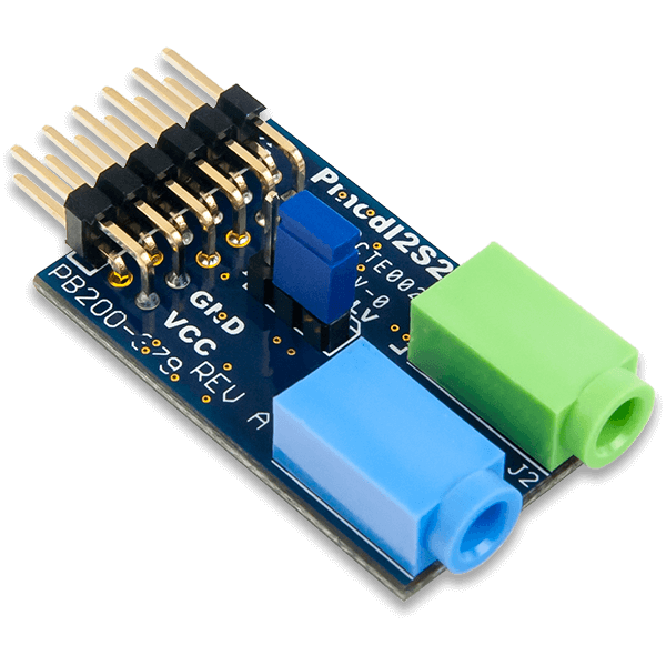
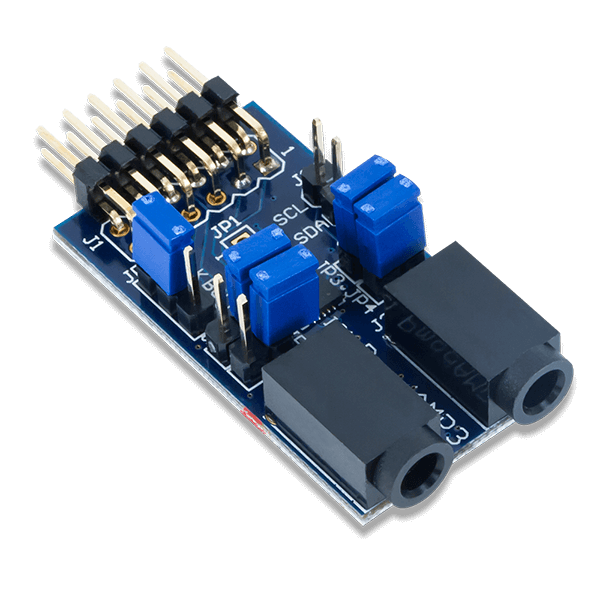
scillators are connected using two 3-wire connectors (+3.3V, signal, GND).

Additionally, following connectors are available:
J4: 8 digital pins tied to 3.3V via 10K resistors - 2 encoders with central (press) button, and 2 LEDs or 2 buttons may be connected
J6: 4 analog inputs - for 4 analog pots on front panel
J5: 8 analog inputs for rear panel - to connect pedals / external buttons / etc...
J8: full 12-pin PMod - unused so far. E.g. for SD card connection.
J9: half (6-pin) PMod - unused, for future extension
J10: differential ADC inputs + power pins, just in case
J11: power (3.3, 5V) + GND

Front panel:
    headphones connector
    1 pot: headphones volume
    1 LED (red + green) - mute indicator?
    stereo audio jack - for headphones
    3 pots: for arbitrary controls depending on app
    2 encoders with press buttons: depending on app

Rear panel:
    Left and Right linear out mono jacks
    Line In stereo jack
    8 connectors for pot or switch pedals

Posted: 9/4/2018 2:56:24 PM
dewster

From: Northern NJ, USA

Joined: 2/17/2012

Vadim, what software are you using for PCB layout?  Is it difficult to learn?

Posted: 9/4/2018 5:13:25 PM
Buggins

From: Porto, Portugal

Joined: 3/16/2017

Vadim, what software are you using for PCB layout?  Is it difficult to learn?

DipTrace freeware version (freeware is limited by 2 layers and ~300 pins).
It's very easy.
I tried to switch to KiCAD, but it's much more complicated, and I've returned back.
I'm using PCBLayout part only for manual tracing (don't draw schematics, and don't use autoplacement/autoroute).

Posted: 9/4/2018 8:01:05 PM
oldtemecula

From: 60 Miles North of San Diego, CA

Joined: 10/1/2014


I used https://www.dexpcb.com/ over the years, I often sent him money to advance his research but I think it is all FREEWARE.

Don't think you are going to do better than this for ease, I have no background in electronics, garage hacker.

Unlimited layer count and unlimited hole count, Allows use of any pcb manufacture using Gerber files if memory serves me.

Within it you draw your schematic and it will lay out and create the pcb, just indicate how many layers to get the board most practical in size. I always prefered doing my own routing and repositioning some parts on the edge. Now it offers an 168 meg parts library which it did not have when I was using it. Aways verify the footprint specs.

Christopher


Posted: 9/5/2018 3:53:31 AM
Buggins

From: Porto, Portugal

Joined: 3/16/2017


I used https://www.dexpcb.com/ over the years, I often sent him money to advance his research but I think it is all FREEWARE.


Thank you! I'll try it.

Looks like it's renamed to AutoTRAX and generation of Gerber files is locked until you pay:


It is the full version but without plottings and Gerber output until you enter a valid software key, which you need to purchase.


But I cannot find what is a price on their site.

You must be logged in to post a reply. Please log in or register for a new account.