Let's design and build cool (but expensive) FPGA based theremin

Posted: 9/30/2019 5:51:18 AM
Buggins

From: Porto, Portugal

Joined: 3/16/2017

I installed "Geany" a couple of days ago and got my Hive sim to mostly compile, it's a lightweight and simple code / compile environment.

Does Geany support code completion, "go to definition" and other useful IDE features?
QtCreator does - using clang parser.

Posted: 10/1/2019 3:59:36 PM
dewster

From: Northern NJ, USA

Joined: 2/17/2012

"Does Geany support code completion, "go to definition" and other useful IDE features?"  - Buggins

Yes, and I believe it lints before it compiles, which is new to me.  It caught several issues in my sim code.

Posted: 4/2/2020 5:32:35 PM
Gibarian

Joined: 12/27/2013

What a cool project. I just successfully compiled the simulator on Linux. There's no sound yet but that's probably a problem that exists between the keyboard and chair. Maybe I will be able to contribute to the GUI stuff. Qt is not unfamiliar territory to me.

Is there a way to get a hold of soldered PCBs? I would love to have this FPGA theremin but I doubt my soldering skills are sufficient to work with SMD components.

Posted: 4/7/2020 10:30:40 AM
Buggins

From: Porto, Portugal

Joined: 3/16/2017


What a cool project. I just successfully compiled the simulator on Linux. There's no sound yet but that's probably a problem that exists between the keyboard and chair. Maybe I will be able to contribute to the GUI stuff. Qt is not unfamiliar territory to me.

Qt is used only for building of simulator (cross platform GUI + audio). Not sure why sound does not work - need to check.
GUI on Zynq core will be written in pure C++, using tiny GUI library.
But it should be easy to write GUI based on this library. Another software part which can be developed on desktop using simulator is audio synthesis code. 
One of two Zynq ARM cores will be used for handling of audio interrupt - once per audio sample.

Now this Cora Z7 based theremin project is not ready for building - still at development stage.

Based on recent investigations, I'm going to redesign all boards.
Sensor boards should not use DFF divider on output - it's sensitive to main hum noise.
Capacitive sensor display should be replaced with resistive one (40-pin IDC connector is pin incompatible in sensor part - SPI interface instead of I2C is used for resistive panel controller) - so, main PCB should be redesigned. Waveshare 4.3 inch resistive screen is out of stock unfortunately - need to look for possible replacement.

Encoders board is not working by some unknown reason - maybe, multiplexing of encoder signals is not a good idea.
Connecting I2C Line In/Out and Phones Out boards directly to currently unused PMod sockets can free a few lines for simple connection of encoders.
PMod adapter board will not be necessary.
Returning back to "easy to solder" principle we can design boards using smt/dip components.


Is there a way to get a hold of soldered PCBs? I would love to have this FPGA theremin but I doubt my soldering skills are sufficient to work with SMD components.


It's possible to order assembled boards from PCB prototyping companies (at least from pcbway.com).
I didn't try to do it, and not sure what would be a cost of assembly.

Are you interested in joining this project?
To start experiments, you can solder simple DIP+through hole components only oscillators and connect them to Cora Z7. Audio boards can be connected directly to PMod ports.
Actually, theremin construction is very interesting hobby.

Recent updates on project state:
Reworking FPGA IP and hardware.
Sensor IP SystemVerilog code rewritten from scratch - better sensitivity.
Small (150-180LUTs) 16bit 4 thread Barrel CPU (250MHz core, 62.5MHz per thread) - as peripherial controller - work in progress.

Posted: 12/22/2020 6:04:54 PM
Buggins

From: Porto, Portugal

Joined: 3/16/2017

Nice cheap (<$50) Zynq 7010 development board from chinese manufacturer QMTech disappeared from Aliexpress.
So I have one device which cannot be ordered anymore - it looks like it does not fit for theremin project anymore

There are some other cheap Chinese zynq boards (even for $10 like this one) but it doesn't have enough pins.
Found interesting but expensive board on 7010 ($150) or 7020 ($210) with a lot of pins.
7020 based one looks like overkill - allows any crazy design you could imagine - 53K LUTs and 106K FFs, 220 DSPs and 140 BRAMs (1024x36bit).
But this device can disappear from market as previous one.

Yet another Z7010/Z7020 device with enough pins (MicroPhase z-lite) - $70 for Zynq 7010 and $110 for Zynq 7020 versions.

With brand devices, like Cora Z7-10 ($129) we can at least hope that it will be available for years.

Update on my plans to build cool FPA based theremin.

FPGA board: Cora Z7-10 (I have one)

I've found the way how to add a lot of encoders w/o consuming of 3 pins per encoder with switch.
Proposed method: latch encoder pins in shift register(s), then shift through one pin output to FPGA.
Only 3 pins needed for any number of encoders/buttons: latch, shift clock and serial data.

Audio I/O: TLV320AIC23B in easy to solder 28 pin TSSOP - for line in / out / headphones out. S/PDIF OUT optical transmitter module.

Touch LCD: Waveshare 4.3inch 480x272 Touch LCD (B) with resistive touch.

Theremin sensor option one:
    Current sensing oscillator on differential amplifier feed (AD6362 or BJTs), differential sine output 1Vpp diff signal on AD6362, 100MSPS 8-bit ADC AD9283 connected via PMOD connectors (requires additional sampling clock and +5V power outside PMOD connector).

Option two:
    Current sensing on differential amplifier feed (AD6362 or BJTs) and buffer (preferable providing differential output) - connected differentially via 2 pins.

Posted: 3/15/2021 12:29:00 PM
Buggins

From: Porto, Portugal

Joined: 3/16/2017

Found cheap second-hand Zynq-7010 FPGA boards.

Search aliexpress for ebaz4205

This board is controller for bitcoin mining farm.

On 3 connectors, 42 FPGA pins are available.

Not sure how long this sale will last for.

Posted: 5/5/2021 5:18:16 PM
Buggins

From: Porto, Portugal

Joined: 3/16/2017

Ordered interesting FPGA board Microphase Z7-Lite 7020 for $103 from aliexpress.


Zynq 7020 has really rich resources which should be enough for any crazy theremin design: 53K LUTs, 106K FFs, 140 36Kbit BRAMs, 220 DSPs

Board has two 40-pin connectors, 512MB SDRAM, SD Card, USB Host, Ethernet, HDMI, USB JTAG and USB UART


Seller sends links to documentation only after purchasing.
So far, I received it only partially (samples for FPGA and PS parts, and for HLS). Of course everything is in Chinese.
No most interesting information so far, like connectors pinout, user guide, schematics.

Posted: 5/13/2021 12:31:17 PM
Buggins

From: Porto, Portugal

Joined: 3/16/2017

Ordered Z7 Lite 7020, downloaded docs.
Documentation is in Chinese, but it's not a big issue. Schematic is readable.

Designing Z7 Lite-based FPGA theremin...

Sensors will be connected via PMOD connectors (8 single ended pins or 4 pairs), using Dewster's FPGA-side PLL approach and current sensing. Implemented using 3 comparators LT1713.

Diff pair 1: drive signal from FPGA - decoded and buffered by comparator
Diff pair 2: current sensing output (shifted) - R_sense and comparator
Diff pair 3: non-shifted output (just returns drive signal, with the same delay as current sensing - to get zero shift between two outputs on resonant frequency.
Diff pair 4: not used
ESD protection: CM1213A-01SO
Inductor and antenna will be connected using coaxial cable / SMA connector.
This sensor PMOD can be used with any FPGA board which has PMOD connector, e.g. Cora Z7.

Z7 Lite has two 40-pin 2x20 pin sockets.
36 pins are FPGA GPIO. The rest 4 are dual GND, +5V, +3.3V
72 pins are more than enough for connecting of peripherals.

Main board (115x80 mm) will have:
2 x 40 pin headers for Z7 Lite core board (56x80mm) mounted on top of main board
2 x PMOD connectors for sensors, with separate 3.3V regulators to minimize noise in sensors
IDC-40 connector for Waveshare 4.3inch 480x272 LCD with resistive touch
IDC-14 connector for Controls (encoders and pots) board
3 x 6.35 audio jacks: Line In, Line Out, Phones Out
2 x 6.35 audio jacks for two expression pedals (pot pedal)
S/PDIF optical out
Power jack
WM8731 codec SSOP-28 package for analog audio i/o
MCP3208 8-channel 12-bit ADC - for Controls board POTs (up to 6) and expression pedals (up to 2)
3.3V regulators for PMODs and codec

Maybe there will be enough unused pins for placing some extension connector - for future extensions.

IDC-14 connector should be enough for controls board.
E.g. 2 pins are VCC+GND, 6 digital IO, 6 analog (potentiometer outputs).
Shift registers on controls board will be used to read states of arbitrary number of encoders and buttons (3 pins actually enough - load, shift, out).

On front and back edge of core board there are a lot of useful stuff:
Type-C USB slave: JTAG, Serial
Type-A USB host
SD Card
Ethernet
HDMI


Posted: 5/18/2021 8:54:51 PM
Buggins

From: Porto, Portugal

Joined: 3/16/2017

Project update:

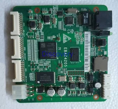
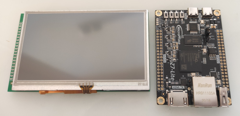
Received my orders: 4.3inch LCD and Z7 Lite FPGA board on Xilinx Zynq 7020 FPGA + 2xARM PSOC.


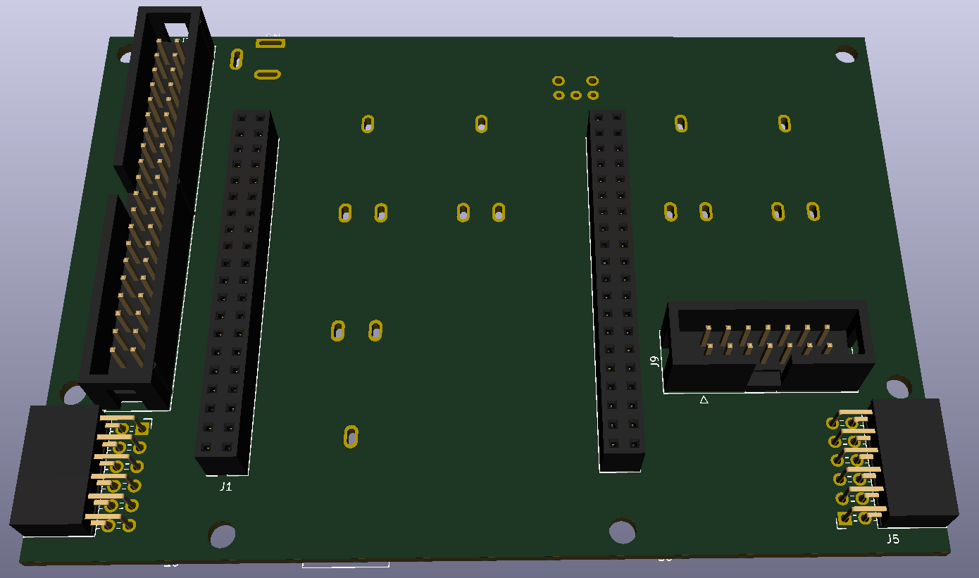
Designed PCB for digital theremin main board based on Z7 Lite

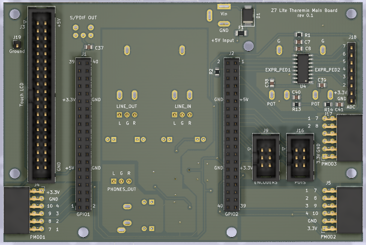
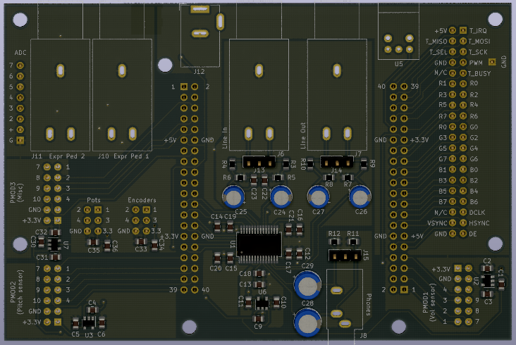
40-pin LCD connector for Waveshare 4.3inch resistive touch LCD: traced with 16-bit RGB565 color to save 8 pins - 64K colors should be enough for theremin.

Three 12-pin PMODs - two will be used for connecting of theremin sensors, third - for future extensions.

Two IDC-6 ribbon cable connectors - for connecting encoders and pots. Each connector has 4 I/O pins available.
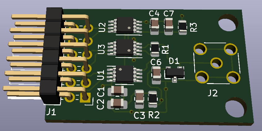
Encoders board will be based on parallel load / serial out shift registers : 3 8-bit registers are enough for reading of 24 signals (8 encoders with buttons).
Potentiometers connector is 4-wire SPI for connecting of 8-channel 12-bit ADC - allows 8 potentiometers.

On-board I2S audio codec provides 24bit 48KHz analog audio I/O: Line In, Line Out, Phones jacks.

Optical S/PDIF output can be used if analog line out quality is not enough.

On-board 12-bit 8-channel ADC provides two jacks for connecting of pot-based expression pedals. Unused 6 ADC channels are routed to 8-pin connector - e.g. for 6 additional pots or pedals.

Power in barrel jack +5V can be used instead of USB for powering of device.

All 3 PMODs and audio codec have their own 3.3V regulators to reduce noise from power line.

Analog audio part is placed on bottom side of board, with jacks below the board - trying to minimize noise.

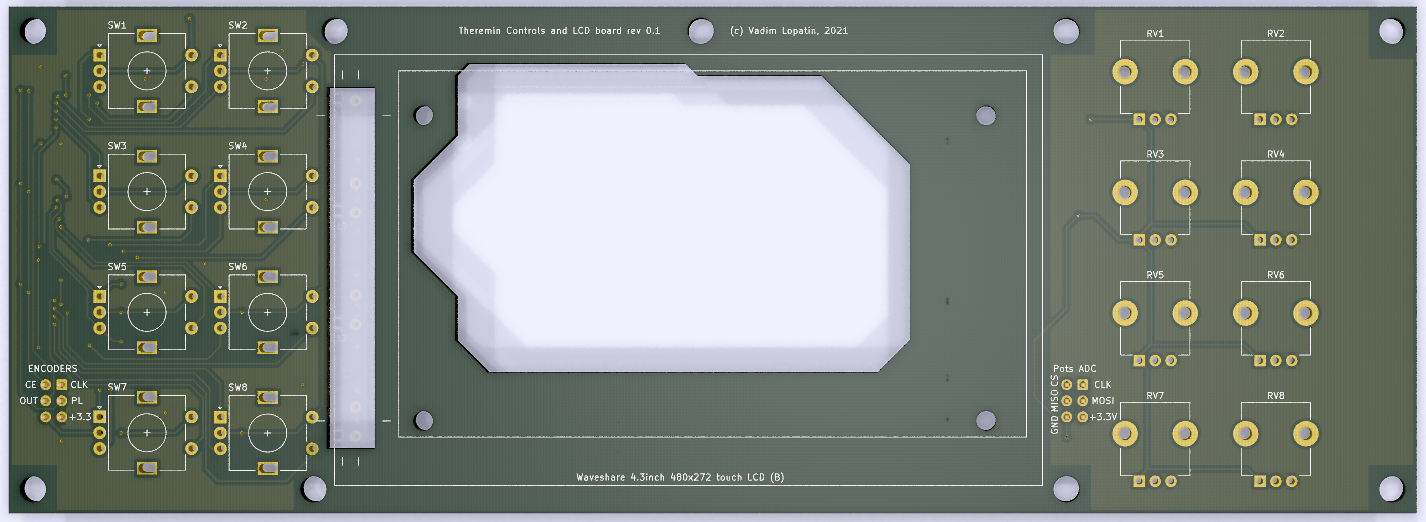
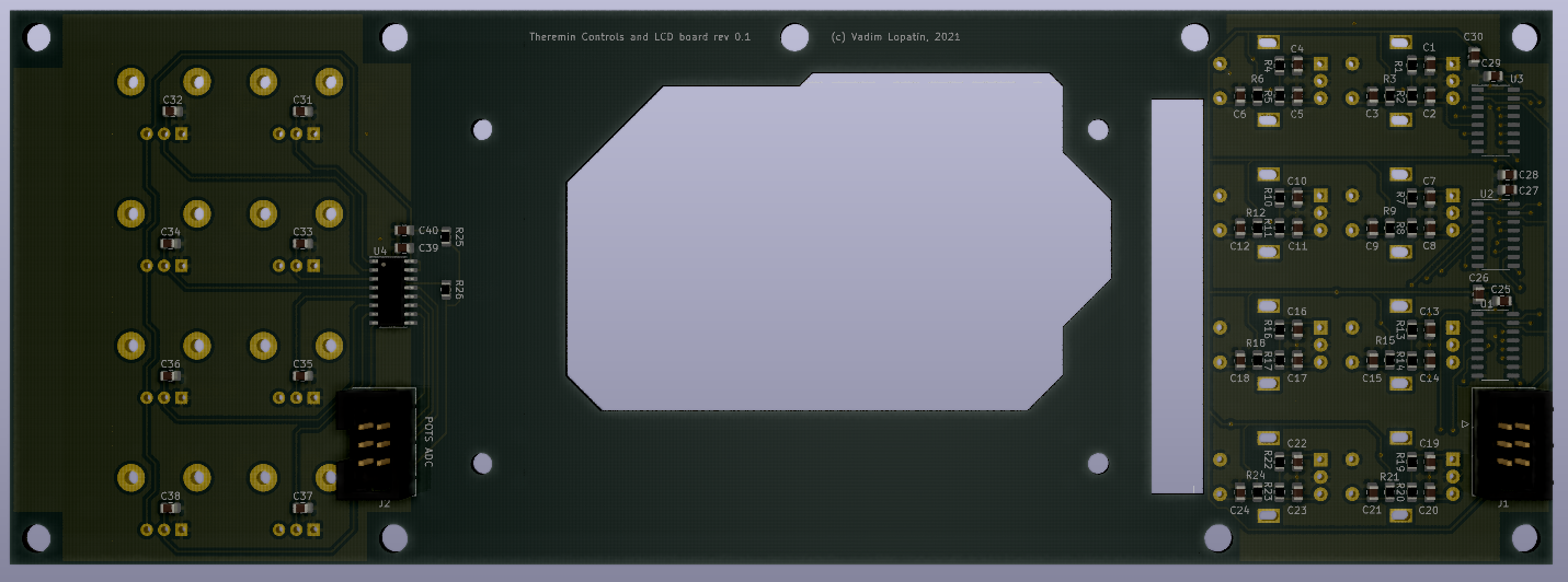
Work in progress: design of controls board with 8 incremental encoders (with pushbuttons) and 8 pots.
Together with touch screen, it should be enough for theremin...

Once controls PCB is ready, I'm going to order manufacturing of PCBs.


Posted: 5/20/2021 4:37:31 PM
Buggins

From: Porto, Portugal

Joined: 3/16/2017

Finished tracing of controls board.
As well, it's used to mount LCD.
Main board is only 80mm height, and has connectors on both front and rear edges.
So, cabinet width should be 80mm, and top cover screen and controls will be mounted to are size limited.
Therefore, pots and encoders are located on left and right sides.
Board dimensions - 222x80mm.


4.3" LCD touchscreen with 480x272 resolution should be enough for theremin UI.
Most important feature I'm planning - low latency pitch preview.
60-100Hz screen updates, with hardware rendering of pitch preview related areas of screen could provide feasible identification of pitch.

There are 8 encoders to the left from screen, and 8 pots to the right (2 x 4 grids with 19mm space).

Is 19mm space between knobs enough from ergonomics point of view?

8 encoders with buttons need to read 8*3 = 24 pin signals. Three 8-bit shift registers with parallel load and serial out are used to transmit all pins via single serial line.
8 pots are read using 8-channel 12-bit ADC with SPI interface.

Due to big size of board, manufacturing of 5 pieces costs $39 - a bit expensive.


Going to order sensor, main board and controls PCBs manufacturing...

You must be logged in to post a reply. Please log in or register for a new account.