That's looking great, Vadim!
If that Control/Encoder board is 2-layer the 222x80 size would be $11.10 for 5 over at JLCPCB, not including shipping. Unless I'm missing something..
What software do you use for your pcbs?
Yes, it's 2-layer pcb.
$39 is pcbway.com price. Price grows since board size exceeds some limit. Small PCBs are usually $5 for 10pcs.
Thank you a lot for pointing at jlcpcb. Will order new pcb there.
I'm using KiCAD (as I see, it's commonly used in open hardware projects).
To get nice 3d render, you have to install FreeCAD as well.
I tried DipTrace recently. But it's free version has pin number limit which I faced.
Now I'm pretty happy with KiCAD.
BTW, would you mind if I borrow cabinet design from your D-Lev III build?
I find it pretty suitable for my project.
"BTW, would you mind if I borrow cabinet design from your D-Lev III build? I find it pretty suitable for my project." -Buggins
Not at all - borrow away! I don't think anyone owns the usual long-box design to house theremins. They're kind of boring but they do the job.
Not at all - borrow away! I don't think anyone owns the usual long-box design to house theremins. They're kind of boring but they do the job.-- pitts8rh
I like EW-style cabinets and classic pipe antennas.
Once again, thank you for pointing at jlcpcb.
Ordered boards.
Total order from jlcpcb is $38.73 - same as only production of LCD + controls board via pcbway.
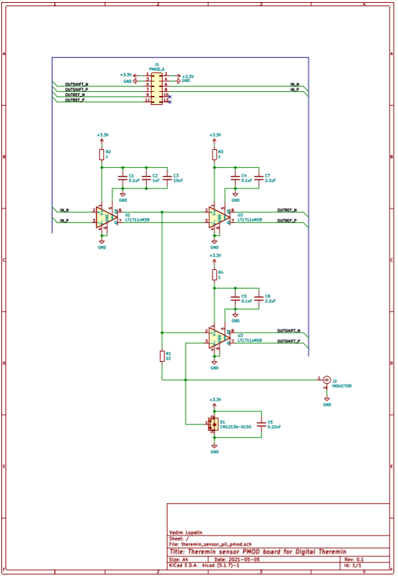
20x30mm 10pcs - sensor (PLL analog frontend) board : $5 (gerber files link)
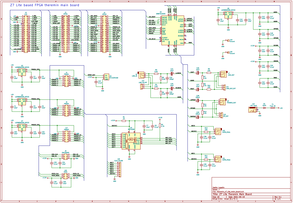
120x80mm 5pcs - main board for Z7 lite : $7.9 (gerber files link)
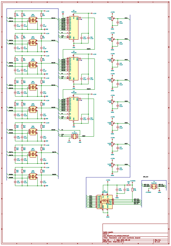
222x80mm 5pcs - LCD and controls board : $11.1 (gerber files link)
$24 0.47KG + shipping $14.73
Build time is 3 days, and even has not been increased after changing of mask to black.
If someone is interested, schematics for all boards:
I lucked out when I started with JLC because it is the only place I've ever used or will need to use and they have been incredibly good. I have received shipments in as little as 6 days from the time I sent gerbers, although lately they have been more like 8 days.
I look at these boards under the microscope and the registration and drilling accuracy is just unbelievable considering the huge size panels that they actually process. I've never run across a single drilled pad that wasn't visually right on dead center. I don't know how they do it. Every time the DHL shipping to the US has cost nearly as much as the board orders themselves, and I consider the DHL shipping cost a bargain too.
I hope it works out as well for you!
Theremin sensor design.
Sensor will use Eric's (dewster) ideas:
* PLL implemented inside FPGA
* Analog frontend outside FPGA just buffers drive signal from FPGA and feeds it to LC tank
* Original (drive) and shifted (after LC tank) signals returned back to FPGA can be used to calculate offset between drive signal frequency and LC resonance frequency
* Current sensing approach can be used to minimize additional C in LC tank (the only C is now antenna capacity). It's one side LC tank connection.
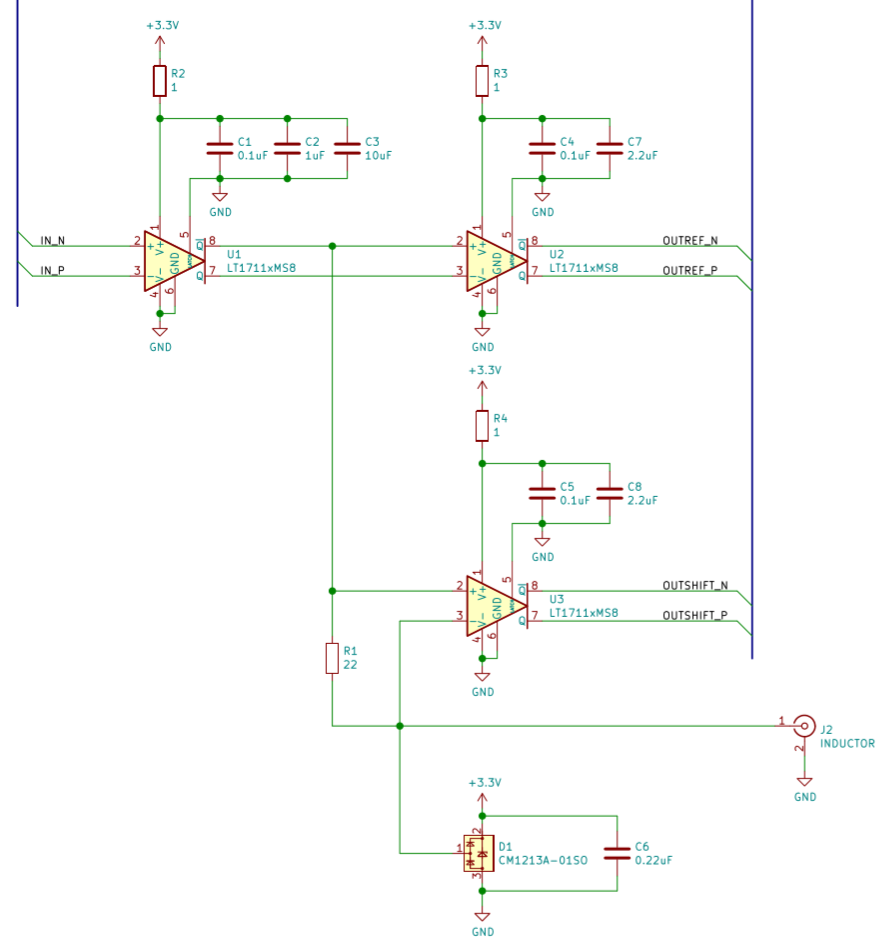
Proposed schematic is probably an overkill - 3 comparators (LT1711 or LT1713) are used.
It's an attempt to minimize noise and increase sensitivity.
Input and two outputs of sensor are complementary (differencial) to reduce noise introduced by line between FPGA and sensor.
U1 buffers differential drive signal from FPGA and feeds LC tank.
U3 is used as current sensor to measure LC tank drive current.
U2 is intended to provide copy of drive signal delayed by the same time as current sensor's propagation delay.
I'm assuming that usage of identical components should compensate propagation delay drift.
When drive signal frequency is equal to LC resonant frequency, shift between U2 output and U3 output will be zero.
CM1213A provides ESD protection.
Although Zynq FPGA has hardware PLL modules, I'm going to implement "soft" PLL - using other FPGA resources.
Xilinx series 7 devices have SERDES modules which allow to implement serial I/O at 1.2GHz (600MHz * 2 in DDR mode).
OSERDES should be fed with 8 bit values at 150MHz, and ISERDES will give 8 bits at the same frequency.
OSERDES based soft drive signal generator virtually is 1.2GHz counter, but its precision seems to be insufficient. Frequencies ~1MHz will be encoded as ~10bit period value.
ISERDES outputs can be used to measure phase shift with 1200MHz counter precision. After averaging, it gives enough bits.
Drive signal can vary its frequency in small range around LC resonance point.
We can calibrate sensor - measure shift between drive and LC shifted signal for different excitation frequencies - and prepare a kind of table - dependency of phase shift from drive to resonance freq distance (or just evaluate LC tank Q, and then use it in some formula similar to atan()).
After calibration data is collected, we will be able calculate LC frequency based on current drive frequency and current phase shift, by applying calculated offset from resonance to drive frequency.
Drive frequency should be tuned to track LC resonance. Some dithering may be added to drive frequency control - to sweep near resonance even if LC frequency is not changed.
Averaging of calculated LC resonance frequency can give us precise measurement of antenna C.
While waiting for delivery of ordered PCBs, I'm working on PLL Theremin Sensor implementation in FPGA.
PLL sensor should generate drive signal which is fed to LC, then measures phase shift between drive signal and LC tank current.
Zero phase shift corresponds to equal frequencies of drive and LC resonance frequencies.
PLL should adjust drive signal frequency to keep zero phase shift (track LC resonance frequency).
Unlike dewster's approach with using of hardware PLL modules inside FPGA, I'm trying to make a kind of "soft" PLL.
Xilinx Series 7 FPGA has serialization and deserialization primitives which allow to update pin state at 1.2GHz feeding 8bits every 150MHz cycle, and read pin at 1.2GHz providing 8bits of deserialized data each 150MHz clock cycle.
Code is available on GitHub (uses Xilinx ISERDESE2, OSERDESE2 primitives)
Currently, two building blocks of PLL sensor are implemented:
smooth_oscillator.sv: periodic signal generator
Target signal period value from input is clamped with min and max period values, averaged with 2-stage IIR filter, and generates smooth (1.2GHz + dithering) drive signal for analog frontend.
smooth_phase_shift.sv: phase difference measure modules
Measures phase difference of two signals sampled at 1.2GHz rate, averaging measured phase shift with 2-stage IIR filter.
Consumed FPGA resources: ~200LUTs for oscillator and ~200LUTs for phase shift measure.
Period value for oscillator, and phase shift from phase measuring are fixed point values with 10-bit integer part and 20-bit fractional part.
LSB in integer part corresponds to 150MHz CLK cycle duration.
10+20 bits is enough to support LC tank frequency range 150KHz .. 6MHz with enough precision.
IIR filter with 10 bits K shift corresponds to 80% response per 48KHz sample.
IIR filter with 11 bits K shift gives 50% response per 48KHz sample.
Now I have to implement missing parts of PLL:
1) calculate relative phase shift = phase_shift / drive_period
2) convert relative phase shift to correction coefficient (using table or atan) according to calibration (basically, measure of LC tank Q)
3) calculate target frequency for oscillator - measured LC resonant frequency by multiply of current drive period to correction K
4) pass calculated LC resonance frequency period as target drive signal period to oscillator
Calculated resonance frequency or just oscillator averaged frequency gives us sensor output - as period value.
Additional processing is required to get extract position from oscillator frequency period value:
scale measured period using calibrated min/max values, linearize it (using log or some interpolation table), and hand position (axis value) is ready.
"Unlike dewster's approach with using of hardware PLL modules inside FPGA, I'm trying to make a kind of "soft" PLL." - Buggins
Vadim, do you mean "soft" in terms of software running on a processor in your FPGA as part of the PLL feedback loop? I tried this early on, and while it did work and gave me the ability to have lots of nuanced control over the DPLL, I ultimately abandoned it for the straight hardware approach. I didn't want to introduce yet another sampling and delay in the loop, and the waveforms (by total chance) worked out so that XOR phase detection works over a much wider range than it normally does. But it is an attractive approach, and I'm not trying to dissuade you from giving it a go.
You probably don't need as much NCO frequency resolution as you might think, as the LC acts kind of like a filter or flywheel, so the NCO can probably "bang-bang" between even fairly coarse settings. And you probably don't need to linearize the phase error as the DPLL will be locked during normal use.
My DPLL is quite simple actually, I don't even bother to filter out the 48kHz dither as it is considerably suppressed by the low bandwidth of the DPLL (pole @ ~100Hz). I've said this before, but you don't want or need direct error correction (the 'P' in PID) because it will give you sticky spots in the field. I'm only using the integrated phase error as feedback.
Another thing that worried me was the phase detector type. I wanted to use XOR rather than edge detection due to the inherently higher noise immunity, and was quite happy that things worked out so that I could.
Vadim, do you mean "soft" in terms of software running on a processor in your FPGA as part of the PLL feedback loop?
--dewster
By soft (vs hard) I mean FPGA LUT+FF pipeline vs FPGA hardware block like PLLE2 (like softcore CPU in PL vs hardware ARM in PS).
I believe it could give some advantages / flexibility.
I tried this early on, and while it did work and gave me the ability to have lots of nuanced control over the DPLL,
I ultimately abandoned it for the straight hardware approach.
I didn't want to introduce yet another sampling and delay in the loop, and the waveforms (by total chance) worked
out so that XOR phase detection works over a much wider range than it normally does.
But it is an attractive approach, and I'm not trying to dissuade you from giving it a go.
--dewster
Did you use SERDES primitives or just read/write at data processing clock frequency (e.g. 200MHz)?
Usual FPGA frequencies are not enough IMHO.
But hardware SERDES modules allow to make I/O working at higher frequencies (e.g. CLK * 8) using SERDES shift registers.
You probably don't need as much NCO frequency resolution as you might think, as the LC acts kind of like a filter or flywheel,
so the NCO can probably "bang-bang" between even fairly coarse settings.
And you probably don't need to linearize the phase error as the DPLL will be locked during normal use.
--dewster
Current default precision parameters in my code are probably overkill, but I can reduce them later after testing on real device.
After some point, adding of bits to LP IIR filter just gives more bits of noise instead of useful data.
More bits, needed for precise hand position detection will be collected on later stages, after LP filtering of PLL output.
Let's consider what we can collect during one 48KHz sample.
Drive signal of 1MHz has period ~1200 1.2GHz clock cycles - ceil(10.25)=11 bits in integer part of period value (11 bits if averaged by both edges - one bit comes to frac part).
During 48KHz cycle, there are ~21 1MHz drive cycles - averaging would give us ~4 more bits in fractional part.
So, precision of 11.5 fixed point should be enough.
To support higher LC frequencies, we need to add more bits to frac part (higher bits will become 0). E.g. extending
of highest supported frequency to 4MHz requires 2 additional bits in frac part.
To support lower LC frequencies, we need to add more bits to int part of period value (e.g. 250KHz requires 2 additional bits of int part).
So, 13.7 drive signal counter precision can hold enough information for drive 250KHz..4MHz for 48KHz sample period.
In 11.5 fixed point value for 1MHz clock, upper ~5 bits will have constant value in LC working range (frequency varies by 8..10%).
So, we will only collect ~11 bits of signal frequency information during 48KHz cycle.
Further averaging (e.g. 100Hz LP) will provide ~9 additional useful bits - total 20 bits of non-linearized axis value.
Assuming that LC frequency to hand distance is LOG() and every 10cm of distance eat 2 bits of LC frequency change, at 80cm we will have only 20-8*2=4 bits left to distinguish hand positions near 80cm distance.
Actually, it's enough, because "natural" averaging during longer period.
All above is true for sensor output precision before linearizing.
Drive counter itself of course can be controlled with lower precision, but we will need its more precise averaged value to calculate phase shift - corrected LC resonance frequency value.
Phase shift value of course does not need so many bits because with high LC Q it's zoomed near zero phase shift.
Zooming effect near resonance increases sensitivity of phase shift.
My DPLL is quite simple actually, I don't even bother to filter out the 48kHz dither
as it is considerably suppressed by the low bandwidth of the DPLL (pole @ ~100Hz).
I've said this before,
but you don't want or need direct error correction (the 'P' in PID) because it will give you sticky spots in the field.
I'm only using the integrated phase error as feedback.
--dewster
Current idea is to calculate near-realtime slightly averaged (~48KHz) phase shift - corrected LC resonance frequency.
Drive signal frequency can be set to this calculated LC resonance frequency value.
We can add dithering to drive signal target frequency.
E.g. it can be applied to drive control: instead of passing of measured LC frequency as drive oscillator parameter, dithering it.
Another thing that worried me was the phase detector type.
I wanted to use XOR rather than edge detection due to the inherently higher noise immunity,
and was quite happy that things worked out so that I could.
--dewster
I like idea of current sensing LC phase shift output. Especially one wire connection from sensor analog frontend to L + antenna.
Current sensing gives zero phase shift at resonance, so I have to detect it.
Unlike hardware flipflop based zero phase detection in PLL ICs (CD4046) which has dead zone near zero, my approach does not have dead zone.
It detects phase difference near zero with 1.2GHz cycle (iserdes rate in DDR mode) precision.
Instead, it has dead zone near PI/2 (my current implementation requires equal ref and shifted signals for at least one 150MHz CLK cycle to switch state).
It should not be a problem because locked loop keeps phase shift near zero.
"By soft (vs hard) I mean FPGA LUT+FF pipeline vs FPGA hardware block like PLLE2 (like softcore CPU in PL vs hardware ARM in PS). I believe it could give some advantages / flexibility." - Buggins
Ah, in that case the D-Lev LCDPLL is soft (LUT+FF) and not a special PLL hardware block in the FPGA.
"Did you use SERDES primitives or just read/write at data processing clock frequency (e.g. 200MHz)?"
I use the DDR element at I/O. With core clock of 180MHz this gives 360MHz effective resolution, which is sufficient - but you always want everything you can get here, and if I had your 8x serdes I'd be using it for sure.
"Phase shift value of course does not need so many bits because with high LC Q it's zoomed near zero phase shift. Zooming effect near resonance increases sensitivity of phase shift."
Yes, the gain increase at resonance is Q/pi, another reason you might as well treat the entire system as linear, though when it isn't locked the search for lock is significantly slowed down due to the lowering of the loop gain.
"Current idea is to calculate near-realtime slightly averaged (~48KHz) phase shift - corrected LC resonance frequency. Drive signal frequency can be set to this calculated LC resonance frequency value."
For the LCDPLL to be a low pass filter for phase noise, the integrated phase error should be used as the NCO input. The phase error is attenuated to set the loop bandwidth, and I use powers of 2 here because the bandwidth doesn't need to be any closer than that, and right shifting to attenuate is free in digital logic.
"We can add dithering to drive signal target frequency. E.g. it can be applied to drive control: instead of passing of measured LC frequency as drive oscillator parameter, dithering it."
I apply the 48kHz triangular dither directly to the NCO drive (frequency) control. Then I'm looking at the phase difference between the two ends of the coil for 90 degrees, which is easily detected via XOR. I sample the phase inputs (via DDR) before XOR rather than after because the DDR elements are at the pins. I've got the dither frequency set significantly above the LCDPLL loop bandwidth so it isn't tracked by the loop. Too much dither (amplitude) can make the LC really bobble around, and I don't know how to quantify the upper limit of useful dither (this is variable via a front panel knob, with 2x for each detent via shifting in digital logic).
"I like idea of current sensing LC phase shift output. Especially one wire connection from sensor analog frontend to L + antenna. Current sensing gives zero phase shift at resonance, so I have to detect it. Unlike hardware flipflop based zero phase detection in PLL ICs (CD4046) which has dead zone near zero, my approach does not have dead zone. It detects phase difference near zero with 1.2GHz cycle (iserdes rate in DDR mode) precision. Instead, it has dead zone near PI/2 (my current implementation requires equal ref and shifted signals for at least one 150MHz CLK cycle to switch state). It should not be a problem because locked loop keeps phase shift near zero."
You can use an XOR if you generate an internal quadrature NCO signal, I had code to do that at one point when I was still going down the heterodyning path IIRC. XOR is superior in this application because it is immune to edge noise (the NCO will be clean but the coil sense won't be) though XOR can lock to harmonics.
One possible down side to single point sensing is: any differential delay for the phase comparison paths can become a drift issue if it has any thermal dependency.
You must be logged in to post a reply. Please log in or register for a new account.