DIY theremin project

Posted: 12/5/2018 5:10:36 PM
Dominique

From: Switzerland

Joined: 11/5/2018

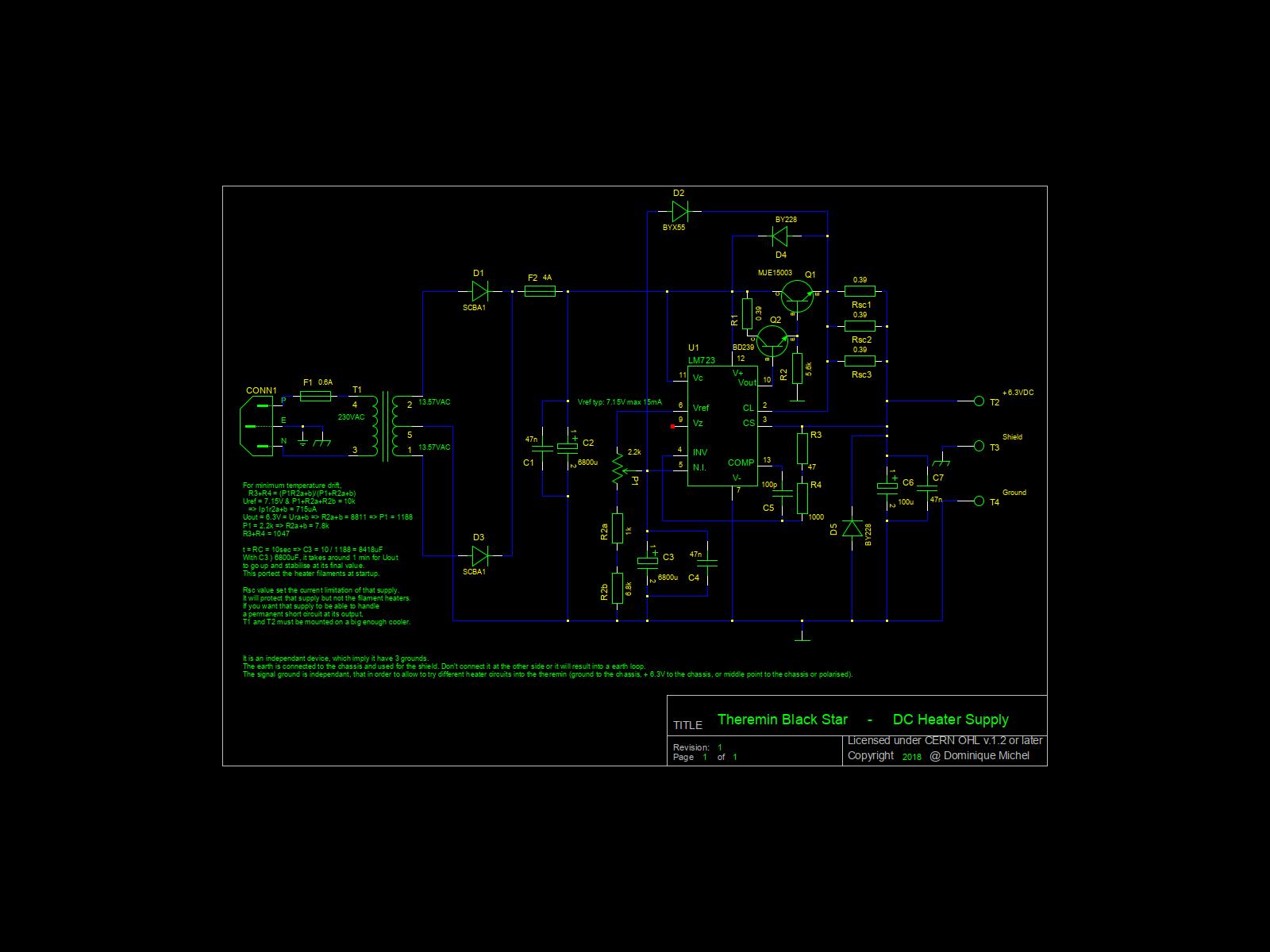
I made a DC heater power supply and will post the schema later. I try to play my theremin in the garden, that in order to be far away from the electromagnetic perturbations of the house. The result was amazing, the sound was just crystal clear, and noise and hum free for any combination of VCA volume and gain potentiometer. It also showed me the volume is sometime too slow to react to hand movements. As I currently use only one triode for the VCA, the relatively huge output capacitor of the preceding stage must be influencing the RC time constant (a few msec) of the VCA detection. That, and the volume acting like a gain setting with non linear bandwidth, imply I will definitely make a 2 triodes circuit for the VCA.

It was noise and hum free in the garden, but it was still too much noise and hum when onto my workbench. That imply I must investigate the voltage on the antennas. I have 5 meters antenna cables and must try with shorter cables, it will level up the antennas voltage. That volume oscillator is the first one I made, one of the caps is not of optimal quality and must be changed. When making the other oscillators, I precedently constated than the ECC85 is less exigent in that regard than the triode mounted EBF89. To change that capacitor should also give me a higher voltage on the antenna, that in order to get at least the same voltage that at the pitch antenna. With the gain at its max, the instrument is much less noisy than with the gain at its minimum. That imply the noise must come from the volume antenna. If I can get it to be noise and hum free onto my workbench, I can assume it will work the same in almost any other environment.

Posted: 12/9/2018 2:52:08 PM
Dominique

From: Switzerland

Joined: 11/5/2018

OK, I made some huge progress with the remaining hum and noise. To put a metallic shield at the bottom of the chassis was a real improvement, especially where the beat frequency is done.  

A new VCA with 2 triodes mounted in classical coupled cathode amplifier, which mean with inverted inputs compared to the Forbes, is in the way. The audio come in to the grid of the tube that have its anode directly to the power, and the output of the detector to the grid of the other tube, the one that have the output resistance. The lowest value of the common Rc must be seen as a grid current limitation on the control input, the other input being always negative in respect to its cathode. That value provide a highly distorted tube sound (without the noise that will result from a grid stopper in serie with the grid), and its highest value fix the minimum gain at maximum antenna's volume and is for the clear sounds.

EDIT: The common cathode resistor is in fact more a wave shaping stuf than something else. The bias is fixed by the DC voltage coming out of the volume detector, and the common Rc set the current in the VCA. It have 2 regimes of work: with and without Ig at the VCA's detector input.

Posted: 12/14/2018 12:34:34 PM
Openair

Joined: 12/14/2018

Have you already traced the boards or estimated the design of the device? Now I have a big current project coming to an end, maybe I will help you, I myself am a circuit design engineer, I can work in P-CAD, AltiumDesign and Solidworks)

Posted: 12/17/2018 2:29:47 PM
Dominique

From: Switzerland

Joined: 11/5/2018

Thank you Openair. I have no boards for now because I am using the chassis of the original radio as prototype. I know I should be able to win something like 10dB on the signal/noise ratio by making a printed board, but it is already low enough (when coupling the VCA output to a JVC hifi amplifier, the noise I heard with full volume on the JVC is the noise of the JVC) for me to begin the second stage, which will be to finalyse the hardware as it is (almost done), put it back into the radio case (ready to do), and just play it. At the same time, I will begin to take contact with experimented theremin players. If they agree, I want them to play the Black Star and to tell we what they think (even if they think it is unplayable or whatever) and why. From my own playing experience, which will be limited because I am an absolute beginner, and theirs valuable returns, I must be able to fine adjust it in order to get not only a fun musical instrument to play, but also a good one.

When this will be done, I will maybe begun to go to the next step which will be to go from that prototype made almost entirely from recuperated parts, to a new design made with existing parts available on the market. But it is too early to envisage it for now. Also you must be aware that the only OS I use is GNU/linux, which make me use only free software. For electronics, I use mostly the gEDA suite which include gschem for the schematics, ngspice for simulation and pcb for print development. gschem is sometime a little unstable (you must save often) but very easy to use. ngspice is a spice flavor with a lot of improvements. It can be easily scripted, which is a huge advantage to make repetitive analysis when, like me, you are not afraid of editing the simulation files directly (It is even possible to automate the process of making animated movies from huge repetitive simulations). pcb is not perfect, but easy to use and can output to most industrial PCB formats. The main gschem disadvantage is than you must make separated schematics for use with ngspice or pcb. This is a little bit annoying at the beginning, but you get used to it very fast. Also the gEDA suite doesn't have a common GUI. For me that's not an issue because I learned ORCAD at school with its DOS version, which made me aware of the different steps of the development process and the corresponding console commands.

I just updated the schematics on github. The pictures in that thread should be updated automatically. I will soon provide new pictures, and some sound samples as well.

Posted: 12/17/2018 2:51:51 PM
Dominique

From: Switzerland

Joined: 11/5/2018

The DC Heater Supply:

Posted: 12/26/2018 8:30:17 AM
Dominique

From: Switzerland

Joined: 11/5/2018

I updated the gallery with new pictures. http://www.thereminworld.com/album/diy-theremin-project/16721?photo=16722
And the github https://github.com/domichel/black_star_theremin with audio files:
4CH004M.flac
4CH005M.flac
4CH006M.flac
4CH007M.flac
4CH008M.flac
4CH009M.flac
STE-003.flac
STE-004.flac
STE-006.flac
STE-015.flac

Posted: 12/26/2018 9:09:10 AM
Dominique

From: Switzerland

Joined: 11/5/2018

With an analog tuner, I was able to measure pitches from C1 to C8 without changing the setup. Pitches between C1 and C2 are really hard to play, not because of the theremin but because it is extensive ear training and I am not used to play such low frequency notes. Also, pitches well over C8 was playable but my tuner is out of range with them, I guess something like G8.

The linearity is quite good for the pitch, which doesn't surprise me as C is proportional to the inverse of the distance. For the volume, I can set it to be very sharp or soft reacting to the hand movement with the potentiometer on the supply voltage of the volume oscillator, but I didn't measured its linearity. The setting of R9 (the cathode resistor of the coupled cathode VCA) have 2 distinct regions, with or without grid current. That make 2 very different loads on the detector, which imply 2 different settings must be used for the volume antenna. That is not fully investigated, so I don't know if I will keep it like that or restrict R9 to the region without grid current.

Posted: 12/26/2018 9:18:08 AM
Dominique

From: Switzerland

Joined: 11/5/2018

On github, I put 2 papers from Clapp:
An LC Oscillator of Unusal Stability
Frequency Stable LC Oscillators
The first one is the best description I know of the Clapp oscillator, and the second one talk about the frequency stability of different types of LC oscillators.

Posted: 12/29/2018 7:21:41 PM
Dominique

From: Switzerland

Joined: 11/5/2018

OK, I begin to understand how it work :

Hi/Feedback put off or on the feedback of the output stage. The sound is more dynamic on Hi and softer on Feedback.

Master is the master volume.

Send and Return are for coupling external effects. Send can be also used as output.

Mix set the sound between Return (counter clockwise) and the VCA output (clockwise).

VCA Level set the VCA input level.

VCA Shape set the bias of the VCA.

VCA Gain set the VCA maximum gain via the supply voltage of the volume oscillator. It must be used in combination with the Master volume. 
I get a much less noisy and warmer sound with Master, VCA Level and Gain at or near their maximum, than when lowering them and using a fuzz. I was not so surprised about that, and that confirm me that it is possible to archive relatively high gains with vacuum tubes and to get a good protection against external noises at the same time. What surprise me is that it is even possible to get that with a theremin. Also, with VCA Gain at the middle, the volume oscillator is still working, the antenna voltage is lower, but the hum rejection is still pleasing, and I am the first one to be completely bluffed by that.

The 2 settings on the antennas are not shown on the picture:
Volume fine tuning and Pitch tuning. The pitch tuning on the antenna is relatively sharp but still usable. It must be set with the Pitch Fine Tuning at the middle.

"Not used" fine tune the fixed oscillator of the pitch. I don't use it. That setting exist only because of all condensators I was having in stock, the only one that was of good enough quality for C5 was the tuning cap of the AM radio. The pitch antenna oscillator was easier to optimize, the difference being the bias R2+C6 which doesn't exist in the pitch antenna oscillator, and the supply voltage.

Posted: 1/3/2019 4:28:52 PM
Dominique

From: Switzerland

Joined: 11/5/2018

I put 2 small videos on github. They was made with ngspice and mencoder:

Youtube doesn't like the second one. It is here: Clapp_raw_alt_fps6.avi It is a psychedelic version of the same simulation.

You must be logged in to post a reply. Please log in or register for a new account.