Build Project: Dewster's D-Lev Digital Theremin

Posted: 11/24/2018 6:38:09 PM
ILYA

From: Theremin Motherland

Joined: 11/13/2005

 " I also have an extension board to allow the 1pF cap to be placed closer to the antenna," - pitts8rh


How about a coaxial cable as a probe like this? Parasitic cap C with internal capacitance of cable will compose a divider.
(just thoughts. A few years ago I used this topology in oscillator).

Posted: 11/24/2018 6:57:48 PM
pitts8rh

From: Minnesota USA

Joined: 11/27/2015

Hi Ilya,

I'm guessing that something like that could work fine as well.  We used to do something like that at mid-GHz frequencies to create intentional leaks between circuits isolated in separate housing cavities.  It was a little difficult to control the leakage amplitudes though.

It will be easy enough to try when we get to that point.  Did you make that drawing for your reply?  It sure seems to fit this application...

Posted: 11/24/2018 7:41:35 PM
ILYA

From: Theremin Motherland

Joined: 11/13/2005

"Did you make"
yes, a few mouse strokes in the MS Word

Posted: 11/24/2018 7:54:13 PM
dewster

From: Northern NJ, USA

Joined: 2/17/2012

ILYA, one possible (?) downside I can imagine to your clever arrangement would be if the coax C is temperature dependent, and thus a source of drift.  I have no idea if that might be the case.  But wouldn't encasing it in coax just bring a low impedance closer than that of the coil drive end itself?  I'm a terrible nit picker, but that high impedance point seems really tender (for a digital Theremin).

I might try locating the series 1pF right at the antenna feed point as the other side of it has a 100pF to ground on the board, so it's 1/100 Z, but you want keep that away from the high Z end of the coil, so ideally maybe locate the 1pF in the center of the coil windings.  Or go crazy and distribute the 1pF through the length of the coil as a series of 3x 3.3pF or 5x 4.7pF (this would help with ESD voltages too).  I try to keep all unnecessary loading off the antenna to keep the absolute sensitivity and Q as high as possible (though there is probably excess for most applications).

Posted: 11/24/2018 8:24:59 PM
ILYA

From: Theremin Motherland

Joined: 11/13/2005

"and thus a source of drift."

The amplitude information is lost after buffering (74LVU04N), thus the instability of dividing will be not so important, (second order effect).

IMO.

Posted: 11/28/2018 7:45:00 PM
dewster

From: Northern NJ, USA

Joined: 2/17/2012

I'm not as good at MSWord as you ILYA, so here's a sketch:

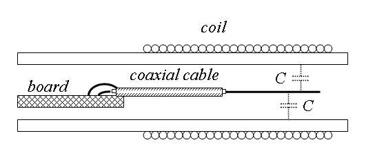
There is an impedance gradient along the coil, with the drive end being low Z and the antenna end being high Z. When it's oscillating you can run your finger over the windings, and touching those closest to the drive end will give lowest "heterodyned" pitch, those closest to the antenna end will give the highest pitch. (I was trying to get FredM to look into this as an alternative to the variable C rods he was working on as a controller input.)

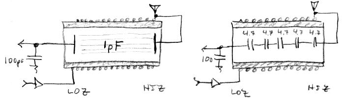
So if the 1pF sense capacitor wired axially thorough the coil was distributed in space (left drawing), it too would have an impedance gradient similar to that of the coil, and therefore would likely interact with it less, but that is impractical.  So instead of a continuous distribution we could use a lumped distribution, say five 4.7pF in series (right drawing). This would help with ESD too, as it would multiply the capacitor working voltage by 5. 

The idea is to make it so the coil sense wire "sees" as little stray C as possible, as absolute sensitivity is vital to this sort of digital Theremin.  Though I'm not saying the lumped C arrangement is mandatory, just that it is more ideal than a single C.

Posted: 12/1/2018 10:12:51 PM
pitts8rh

From: Minnesota USA

Joined: 11/27/2015

The female headers that I had ordered to allow the FPGA module to plug onto a main interconnect board were the wrong pitch (my fault), so I took the time to make boards for the tuner display while waiting for new headers to arrive. 

I thought it might be a good idea to build the tuner on two separate boards - one for the driver circuitry, and another for the LED array since this part is more likely to change at some point.  The LED layout shown here is about the same as Dewster's original, with the exception that the LEDs and the 7-segment are socketed to allow testing out different colors.  Another RJ45 jack is used to connect the tuner driver board to the (yet to be made) main board.  I should be able to keep track of three cables to prevent plugging the antenna driver board cables into the tuner jack, and vice versa.

I'm still not sure how the tuner will be packaged and mounted to the main enclosure, but it will probably have a back-painted acrylic front panel with LED holes and a display window similar to that of the main enclosure.

That's about it for now.


Posted: 12/2/2018 6:47:42 AM
ILYA

From: Theremin Motherland

Joined: 11/13/2005

your x-ray like photos are awesome!

Posted: 12/2/2018 4:45:40 PM
pitts8rh

From: Minnesota USA

Joined: 11/27/2015

Thanks Ilya.  I was a little surprised that they turned out so well because I thought they would be overexposed by the backlight.  I had to turn off the flash though.  I've tried to trace other 2-layer circuit boards by using a bright point-source backlight, but as you know the two solder mask layers usually diffuse the light too much.

Posted: 12/2/2018 6:13:21 PM
dewster

From: Northern NJ, USA

Joined: 2/17/2012

Very nice!  I assume U4 is a 3.3V regulator.  Is the extra line of thru-holes above the display board connector to transfer connectivity from one side to the other?  Socketing all the LEDs lets you play around with the colors, something I should have done too.

You must be logged in to post a reply. Please log in or register for a new account.