Hive is 32 bit, 180MHz, but doesn't have floating point, nor anywhere near that amount of RAM or Flash, so you're way ahead there. But the FPGA logic offloads much of the housekeeping (oscillator logic; LCD, Tuner, SPDIF, UART), and gives 400MHz timing resolution. Having EEPROM large enough to hold SW and presets is nice, though I'm sure you could use Flash for that. What I really like about Hive is that it is 100% deterministic in terms of timing (no cache, no speculative execution, etc.) and the timing model is super simple. There's no overhead for subroutines either due to the hybrid register/stack arrays, so I feel pretty free to factor my code when writing assembly.
AFAIK, HIVE has 8 threads, so isn't it 180MHz*8 actually?
Didn't you consider upgrading to next gen FPGA, with more resources?
I hope, 256KB of RAM will be enough for implementing of reverberation. I believe reverb is must have for theremins. My Etherwave after applying of external reverb using guitar combo sounds much better.
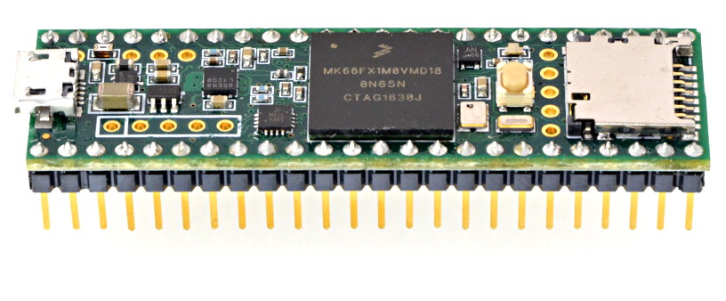
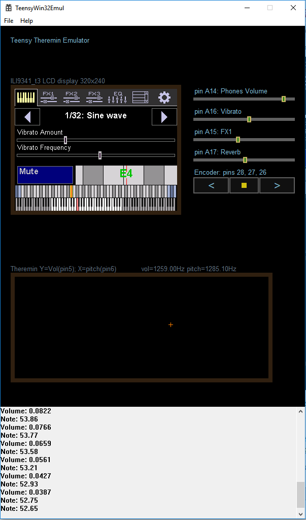
Teensy 3.6 based implementation will require only two time critical IRQs: measurement of theremin sensor output frequency (fired on signal edge, should read 60MHz timer value latched on signal edge, and do some accumulation and averaging) and synthesis of audio frame (frame size is expected to be about 3ms, measured frequency from sensor will be converted to note/volume only once per frame, then interpolated).
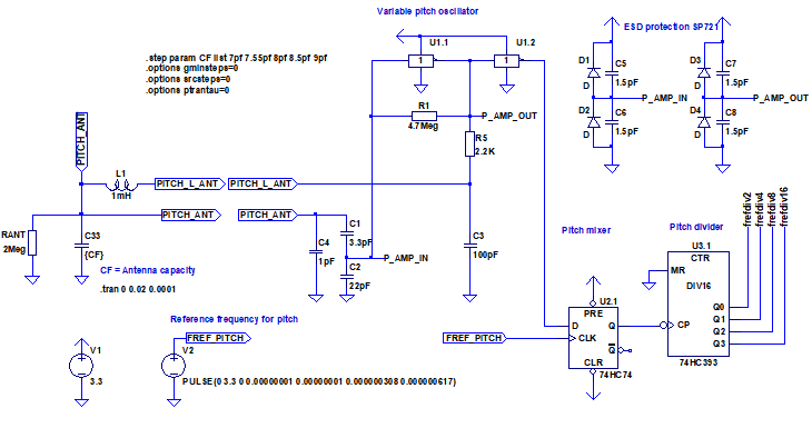
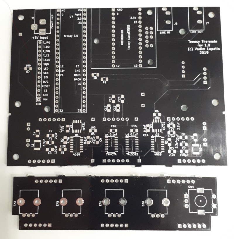
I see you're using an RC to drive the LC tank. I was experimenting with this too at one point, but abandoned it due to the frequency based phase shift and attenuation, though it does work well. Have you considered the 74AHC04? Of the 74AHC parts I've tested, the Vt has been remarkably well centered at VCC/2. And they're natively 3.3V and quite fast (less phase shift, less temperature drift).
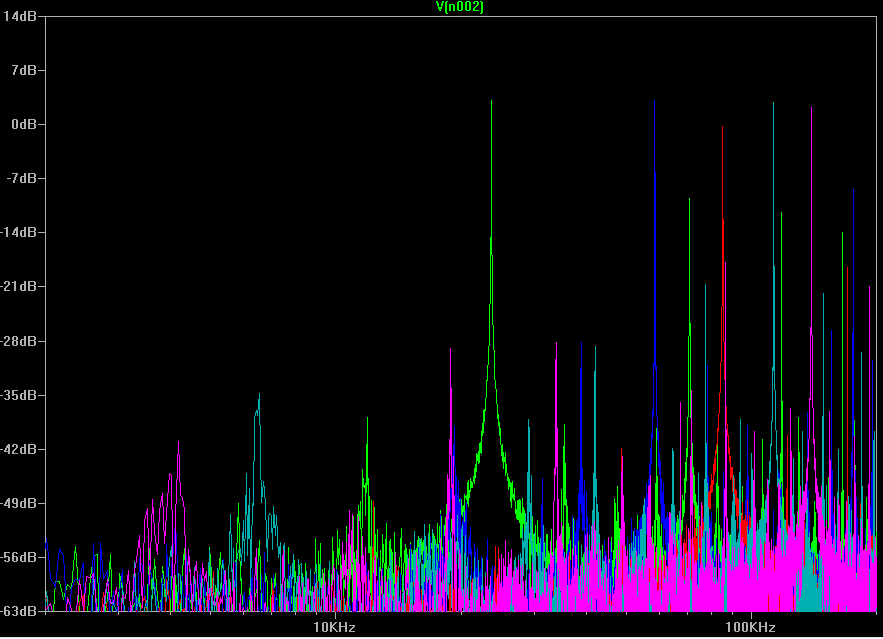
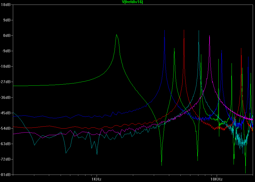
I've played a bit more with LTSpice simulation and found that RC is really needed at front of LC tank.
R may be reduced to increase antenna voltage swing.
Code:
.step param R5 list 50 100 200 500 1000 2000 4000
Cant = 7pF   C3=100pF
R5, Ohm   50     100    200    500    1000   2000   4000
Vant      42.35  41.55  39.93  37.75  36.14  33.89  30.43
R=100..200 looks as best choice for me. It makes sense to use 100 Ohm or 1000 Ohm resistor since such components already present in schematic.
Playing with various C values gave a bit strange result.
Increasing of C gives bigger voltage swing on antenna, but may lead to unstable generation.
It looks like C=100..300pF is good choice. Original value in schematic, 100pF, is good enough
Code:
.step param C3 list 1pF 10pF 33pF 100pF 200pF 500pF 1000pF
Cant = 7pF R5=200 C3=1pF 10pF 33pF 100pF 200pF 500pF 1000pF
C3,pF 1 10 33 100 200 500 1000
Vant 3.63 7.98 17.35 39.69 50.58 60.14 60.45
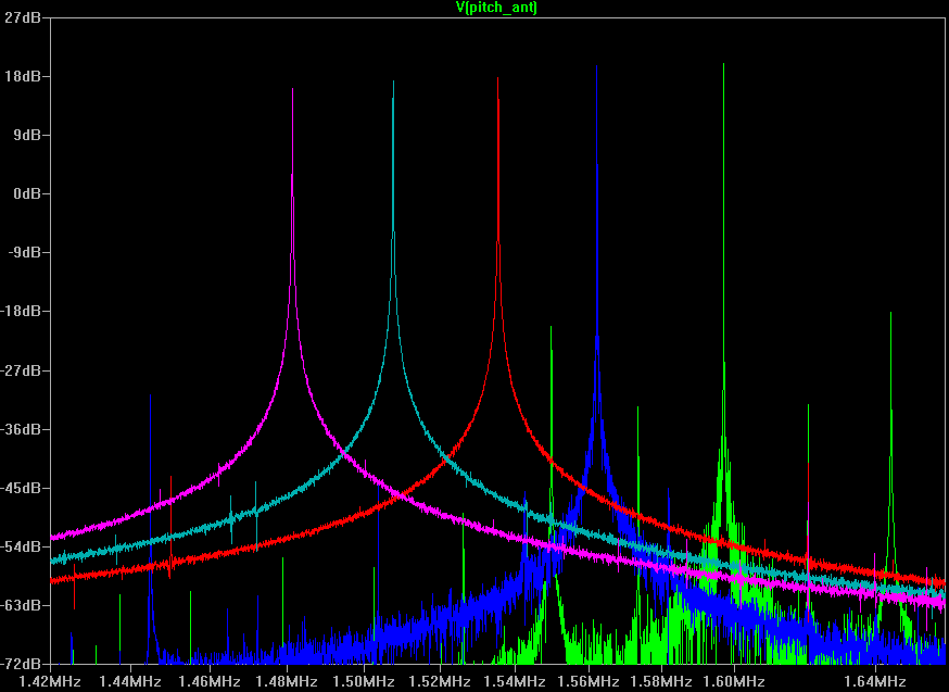
Fosc,MHz 2.048 1.82 1.677 1.593 1.568 1.54 1.52
Checking how C affects sensitivity (difference between oscillator frequency for Cant=7pF and 9pF)
Code:
.step param C3 list 1pF 10pF 33pF 100pF 200pF 500pF 1000pF
Cant = 7pF  R5=100 C3=1pF 10pF 33pF 100pF 200pF 500pF 1000pF
C3,pF     1     10    33     100    200    500    1000
Vant      3.88  8.47  18.59  41.32  51.2   63     56.15
Fosc,MHz  2.03  1.8   1.666  1.59   1.569  1.54   1.53

Cant = 9pF  R5=100
C3,pF     1     10    33     100    200    500    1000
Vant      2.9   6.59  15.5   35.5   48.8   63     60.5
Fosc,MHz  1.959 1.711 1.557  1.472  1.448  1.42   1.4
F7pf/F9pf 1.045 1.064 1.077  1.082  1.082  1.084  1.086
Last row shows sensitivity of oscillator to changes of antenna capacity.
It was a surprise for me to see that even big C values at LC tank input do not affect sensitivity, just decrease oscillator frequency (till some limit near 1.4MHz)
C in range 100..300pF looks reasonable choice. It gives 8..8.5% of frequency changes.
Finally, R=100 and C=330pF gave voltage swing 63V which almost does not decrease when hand approaches antenna, with frequency change 9% when Cant varies between 7pF and 9pF.
Additional change of LC tank output capacitive divider parameters from 3.3pF/22pF to 1pF/10pF gives 110V voltage swing and 11% of frequency change.
Of course, 74AHC can be used as a replacement, once they have soic-14 package.
They just not as popular / easy to buy than 74hc.
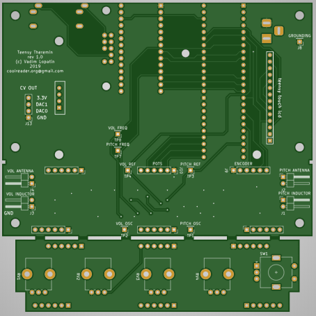
You'll probably want to debounce that encoder via RC, and then debounce the hell out of it in SW. I've found mechanical encoders to be really weird and fussy when spun fast (they can go backwards!). They wear quickly wear too, so you have make the interface as bullet-proof as possible. I've spent weeks, perhaps months, just on encoder nonsense.
I din't try reading from encoder yet. It was my mistake that RC filters are not included into current schematics. Now I just hope s/w debouncing will be enough.
BTW, what R and C values are the best for encoder output filtering? I believe you did a lot of experiments.
Looks like an interesting project, thanks so much for sharing the details, please keep us up-to-date! Digital Theremin circuitry can be really simple and very robust. I'm not sure why the Open.Theremin was never taken to this next level by its creator.
Still using slow 8bit Arduino UNO while much better MCU may be found at the same price looks really strange.
BTW, forum engine support of quotes seems to be broken