


OMG, this is what I have been missing, Thank you for this thread. I am a beginner in DIY music world, I recently found out about the theremin and teensy independently and thought it would be cool to make a project that combined the two of them
Teensy 4.0 600MHz ARM Cortex M-7 MCU - ideal for digital MCU based theremin?
Posted: 11/16/2019 6:57:19 AM

OMG, this is what I have been missing, Thank you for this thread. I am a beginner in DIY music world, I recently found out about the theremin and teensy independently and thought it would be cool to make a project that combined the two of them
It's really nice hobby, theremin construction 
Posted: 11/16/2019 7:03:45 AM
Tuned model with 2mH inductor, F_ref ~1MHz: GitHub link
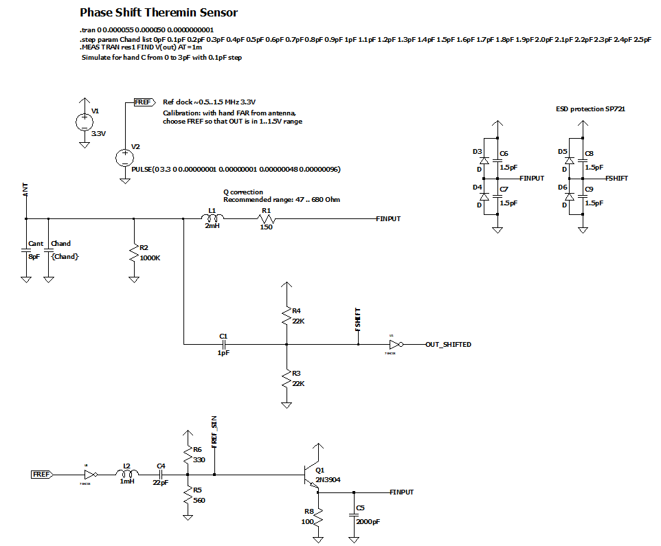
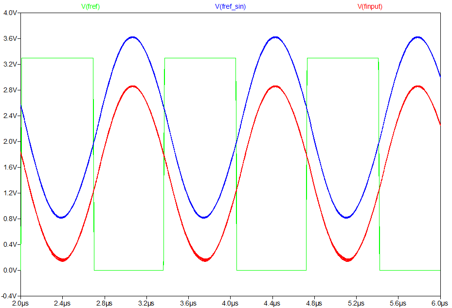
Oscillator input is sine.
Oscillator output is in 0..3.3V, doesn't exceed clipping diodes range.
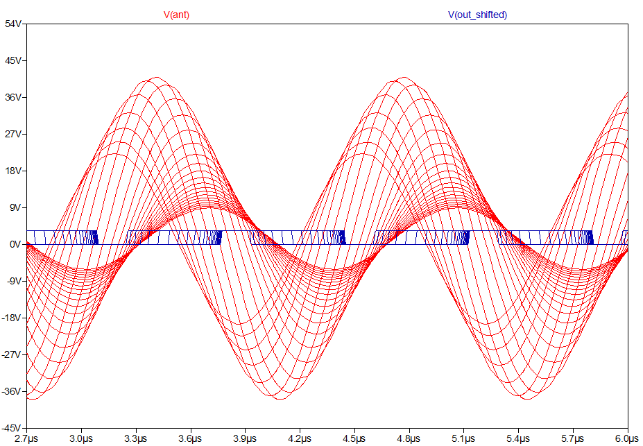
Results of simulation: before and after output buffer.
C_hand varies in range 0..2pF with step 0.1pF
Our goal is to zoom in area corresponding to far hand distances, while keeping the rest 1.4pF inside readable area.
Reference frequency should be selected somewhere near resonance with C_hand=0 to have values for far distance range (>20cm) in the middle.
Zoomed 0.1pF piece depending on Q tuning may be 4..10% of full range.
Posted: 11/16/2019 7:56:39 AM
Vadim, I haven't checked your numbers, but I believe you are absolutely on the right path with your calculations. I'm not saying you are right because it is what I did too, just that it's very interesting to see someone else working the numbers before committing to hardware. I directly see a lot of resolution reduction in the far field on my D-Lev, particularly since I reduced the influence of AC hum, and made the bandwidth track hand position (less BW with the pitch hand farther away). This is masked a lot by the far field pitch being naturally low so the human ear can't hear pitch very well, and the dithering of AC hum can actually help resolution to some degree. Anyway, what I see is much in line with your numbers. Playing out around 1m is probably not a realistic goal anyway, as the rest of the body and other disturbances in the area will dominate. I find playing in the far field is somehow less comfortable than in the mid and near fields, even though the linearity can be made quite good throughout.It seems you're searching for a way to do a pro-grade Theremin with the bare minimum of hardware? I'm not saying you shouldn't attempt this (it can be a fun puzzle to sove), but a small FPGA or other dedicated logic isn't too expensive for people to purchase in their pro Theremin? The case and other stuff will likely swamp the cost of the guts. To me, making the thing easy to own (simple to tune and adjust) is job #1. Making it playable is job #2. Making it sound good is job #3.I applaud your tenacity!
Doing calculations and prototyping before is really must have. Otherwise you would have 3 FPGA boards, 4 MCUs, 5 audio codec boards, 5 LCDs of different sizes and interfaces, and a lot of many other parts, as I have
I believe, phase shift measure might be more precise than PLL approach. As far as I understand, your PLL method should be close to direct measurement of oscillator frequency (please correct me if I'm wrong).
Oscillator frequency varies ~5% for different hand distances. Only 1/15 of C_hand range corresponds to distances > 20cm. It's 5%/15=0.3%
In phase shift detector, 5% of range is really zoomed far distances (>21cm).
So, I believe, phase shift should have 15 times better precision, allowing + 20 cm of distance with the same sensitivity.
AFAIR, you tried this approach... Why did you switch from it to PLL?
In FPGA, you could measure intervals with at least 400MHz precision, doing any averaging you wish.
I'm not sure what should be the goal max playable distance. 60cm is must have. 1m is useless. Limit should be somewhere between 70-80cm.
The only thereminist I ever met, Peter Thermen, likes long distances (50-70cm on Etherwave), but probably because he likes low octaves.
On far distances, if precision of frame (e.g. 1ms) is not enough, actual sound will still be finer grained - alternating (dithering) between two aliased frequencies with some distribution between them sounds like intermediate frequency, at least for low pitch.
I'm to make sensitive (playable at far distances), low latency (max 1-3ms is still probably non audible), rich synthesizer, fast on-screen pitch preview.
If possible, I want to achieve all of this using less soldering (use easy to buy boards/modules), inexpensive when possible (but not necessary), easy to program if possible.
So far, the only reason to use FPGA for me was a sensor. I believe, your Hive based synthesizer program may be easy executed by 600-800MHz arm.
Schematics from my last post doesn't require additional components near MCU at all - one pin output, one pin input.
If sensitivity of this method would be enough for pitch antenna, it's great, we can use it and get really easy to build theremin (much more easy than Open.Theremin).
Possible sound quality 44100/16bit to 48000/24bit or even more (via SGTL5000 is good enough). Teensy 4.0 has SPDIF input and output pins as well - wihch allows to connect receiver and transmitter.
Next step: proof of concept with sensor on prototyping boards, writing of sensor code (PWM module and DMA programming of NXP mcu should be learned).
Posted: 11/16/2019 5:22:07 PM

"I believe, phase shift measure might be more precise than PLL approach. As far as I understand, your PLL method should be close to direct measurement of oscillator frequency (please correct me if I'm wrong)." - Buggins
Yes, my PLL method provides the exact frequency of oscillation that gives the highest voltage swing at the antenna, and also measures this frequency directly.
"Oscillator frequency varies ~5% for different hand distances. Only 1/15 of C_hand range corresponds to distances > 20cm. It's 5%/15=0.3%
In phase shift detector, 5% of range is really zoomed far distances (>21cm).
So, I believe, phase shift should have 15 times better precision, allowing + 20 cm of distance with the same sensitivity.
AFAIR, you tried this approach... Why did you switch from it to PLL?"
I never tried this approach, though I did look into digital heterodyning and period measurement. Frequency measurement is easier and more convenient to sample, and taking the reciprocal mathematically in the processor gives essentially the same result as measuring the period. And I suppose maintaining the voltage swing at maximum was an overriding concern. Phase measurement requires degrading the coil Q, something I decided against a while ago as that reduces voltage swing, and also reduces selectivity, which potentially allows more environmental RF in. Phase measurement also adds an additional non-linear element in to the linearizing process, not sure how hard that might be to compensate for. But some extra resolution in the far field might make up for it all?
"I'm to make sensitive (playable at far distances), low latency (max 1-3ms is still probably non audible), rich synthesizer, fast on-screen pitch preview.
If possible, I want to achieve all of this using less soldering (use easy to buy boards/modules), inexpensive when possible (but not necessary), easy to program if possible.
So far, the only reason to use FPGA for me was a sensor."
Yes, I do see your position.
"I believe, your Hive based synthesizer program may be easy executed by 600-800MHz arm."
Most definitely. I feel a little bad using all that FPGA logic just for my slow-ass 180MHz processor. Though it does give me absolute total control over every little thing.
=====================
Vadim, it's not clear to me why you're using a secondary LC to drive the primary LC. Is it to have a sine wave as the driving waveform? Have you tried square drive here instead, perhaps from an NPN & PNP transistor buffer? Also, you could possibly bias the FSHIFT point via inverter feedback, instead of via voltage divider (I use C divider and slight inverter feedback to keep phase shift low here)? Also, where did the quadrature stuff go, did you decide against it?
Posted: 11/16/2019 6:29:16 PM
Most definitely. I feel a little bad using all that FPGA logic just for my slow-ass 180MHz processor. Though it does give me absolute total control over every little thing.
Teensy 4.0 CPU is predictable enough. It doesn't have SDRAM nor cache.
Instead, its RAM is actually dual port SRAM, with support of one simultaneous reading of instruction and data in the same clock cycle.
Not so predictable is branch prediction and ability to run two independent integer instructions in one cycle (float instruction can be only one per cycle).
It even has hardware support of double precision floating point.
Vadim, it's not clear to me why you're using a secondary LC to drive the primary LC. Is it to have a sine wave as the driving waveform? Have you tried square drive here instead, perhaps from an NPN & PNP transistor buffer? Also, you could possibly bias the FSHIFT point via inverter feedback, instead of via voltage divider (I use C divider and slight inverter feedback to keep phase shift low here)?
I've noticed on simulation that L output is not exact sine due if fed with square.
Secondary LC is just a bandpass filter with NPN buffer just to have something similar to clean sine.
Will try both sine and square to compare. Of course it's better to have less components if performance is the same.
Conversion of reference frequency signal to sine adds some delay (as well as buffers), but it doesn't matter while everything is synchronous with reference frequency PWM, and zero point (PI/2 point) can be calculated during calibration and then corrected.
Divider is not just to have middle point near 3.3V/2, but as well to reduce input swing of buffer below ESD protection or 74HC logic input diodes cutoff.
When amplitude changes from above to below this cutoff, or back, some distortion appears. But probably it's just due to phase shift+amplitude on lower resonance.
I tried to remove divider, and see that middle point is still 3.3V/2.
BTW, I was surprised that LTSpice simulation of 74HC04 doesn't limit input (I thought there should be diodes).
Do you think,
Also, where did the quadrature stuff go, did you decide against it?
I've looked at phase shift approach once again, then read MCU datasheet, and found that there is a possibility of phase shift measure w/o CPU. Initial plan was to convert phase shift to PWM, then convert it to voltage with LP filter, then read using 24-bit ADC (external module).
But since I found pure digital solution, I removed PWM + LP filter + ADC part, leaving only LC shifter.
Quadrature stuff is spare plan, if phase shift is not enough for pitch antenna (I'm sure, for volume antenna it should work).
Quadrature approach requires additional hardware analog cirquit: dual channel switch + LP filter for heterodyne.
It utilizes Line In as ADC, so it's adds no CPU load, in cost of occupied Line In.
Having NO cirquitry near MCU at all looks really cool (if works).
==========
Spent 3 hours in meditation (manual winding of coil).
32mm frame, 75mm winding length.
Got 4.272mH on chinese L/C meter from aliexpress.
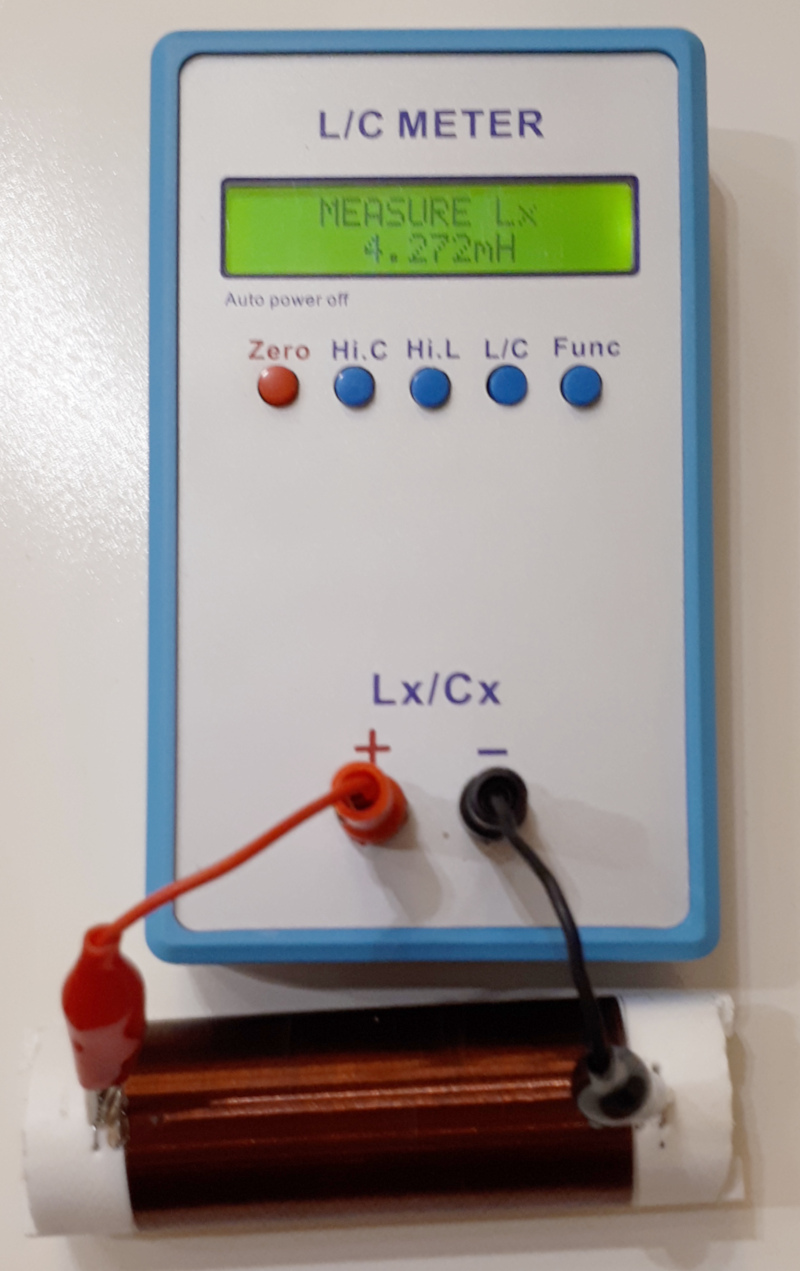
Trying to check with Coil64: looks matching
Input:
Inductance L: 4,272 microH
Frequency f: 0.6 MHz
Former diameter D: 32 mm
Wire diameter d: 0.1 mm
Wire diameter with insulation k: 0.109 mm
Winding pitch p: 0.122 mm
Result:
Number of turns of the coil N = 613.288
Length of wire without leads lw = 61.864 m
Length of winding l = 74.930 mm
Weight of wire m = 4.32436 g
Reactance of the coil X = 16,105.061 Ohm
Self capacitance Cs = 1.341 pF
Coil self-resonance frequency Fsr = 1.358 MHz
Coil constructive Q-factor Q = 82
Loss resistance ESR = 196.403 Ohm
Posted: 11/18/2019 11:14:43 AM
Trying to update model for measured inductor parameters.
LTSpice model: GitHub link
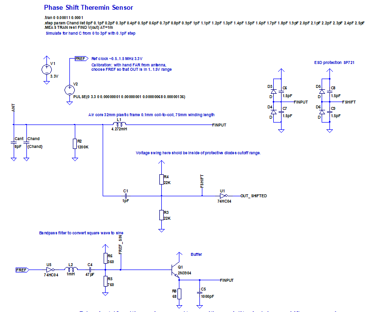
Tried square wave input on LC (no square to sine convertor on input, just invertor as buffer) and without R4/R3 limiter (don't try to limit out buffer input inside ESD protection diodes clipping range) - bad results when difference is far from resonance.
So, I'm keeping input sine and limiting/centering resistors on output buffer input.
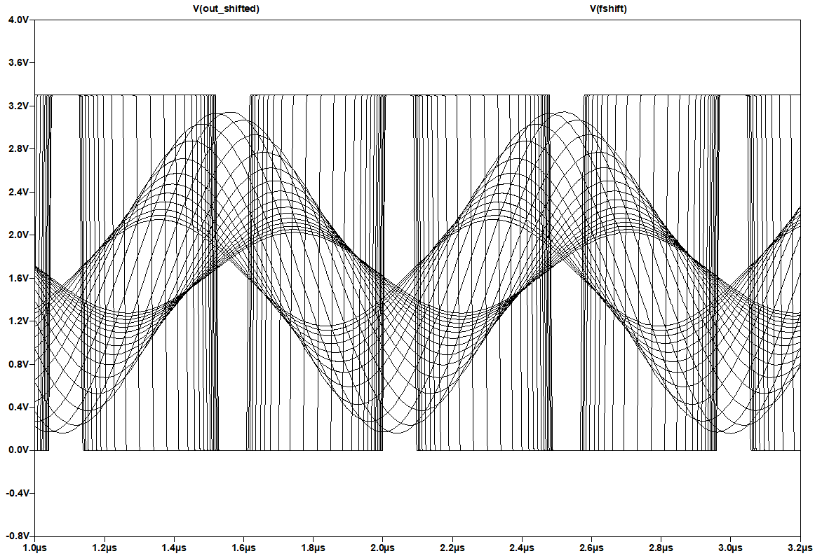
Simulation results for square to sin conversion:
Voltage swing on antenna and sensor output:
Source and output signals of sensor output buffer:
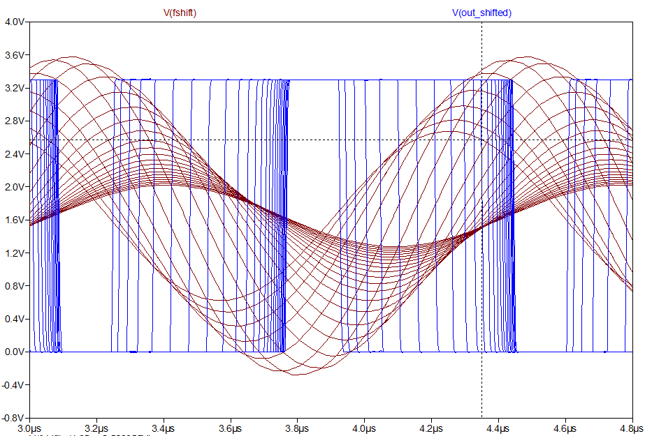
In this simulation, we change C_hand from 0 to 2pF with 0.1pF step.
Working range for calibrated reference frequency: middle wide 0.1pF step (all distances > 21cm) + 14 more steps at the right (distances 21cm where we have 1.4pF C_hand range), it's obviously enough.
Let's check what we have for longer (>21cm) range which corresponds to ~0.1pF region near resonance frequency (PI/2 shift).
4.2% input range limit of middle 0.1pF eats log2(100/4.2)=4.57 bits of input range.
18-4.57 = 13.6 bits
Code:
range    bits left
21     13.6
31     11.8
41     10
51     8.2
61     6.4
71     4.6
81     2.8
91     1
101     -0.8
After 61cm distance we see 6.4 bits left in input value.
In general, this means we will have audible quantization of pitch.
But actually, long distances usually correspond to lower frequency notes. And actually, when synthesis of output signal with "dithered" (varying) frequency,
output probably will sound like "average" frequency.
We can as well to increase averaging time interval. Increasing of averaging 4 times, gives additional 10cm of playable distance.
But the bigger averaging interval is, the bigger is latency between hand movement and
I believe 3..4ms averaging interval will still be non-audible.
So, it looks like it's possible to have playable distance 60-90cm of hand from pitch antenna, using only Teensy 4.0 PWM pins, with simple phase shift sensor.
But how will we read measured values? There will be 690000 measure results per second.
We could use interrupt, but at this rate, CPU would waste half of time on interrupt processing (saving/restoring registers, etc).
Fortunately, there is DMA in Teensy 4.0 MCU.
It can be programmed to save results of every capture to ring buffer in RAM.
In Audio ISR, we can do averaging for all values in buffer to get precise enough sensor value per frame.
Conclusion.
It looks like it's possible to implement phase shift based theremin on Teensy4 with minimal external components.
Pitch antenna max playable range is expected to be 60..80cm.
Going to try with hardware prototype.
Posted: 11/18/2019 7:34:00 PM
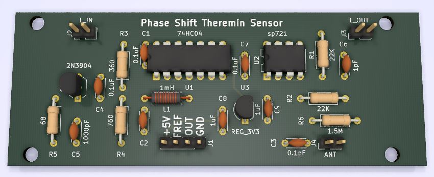
To simplify soldering of sensor prototype, I've created KiCAD project.
Changes comparing to LTSpice model:
* Power input is +5V. 3.3V regulator added to minimize noise via power line.
* Optional capacitor from antenna to ground is routed.
2.54mm prototype board friendly design of Phase Shift sensor PCB is available in KiCAD format on GitHUB.
All components are THT/DIP/TO-92
3d render:
Posted: 11/22/2019 6:27:05 PM
I'm working on library for phase shift sensor support, in arduino style, for Teensy 4.
For testing, connected RC delay line on Pot+C between pins 2 and 3, to see phase shift for different RC values.
Generated 690KHz reference frequency on pin2 and managed to setup capturing of input pin 3 edges - for now, directly reading captured values from registers. Captured values are delay from cycle beginning to edge in 200MHz cycles. I see values alternating between two consequent values - averaging would provide more bits.
Next step: add DMA support to put all captured values into ring buffer in RAM.
In audio IRQ, I'm planning to average all captured values in buffer.
Posted: 11/22/2019 8:14:13 PM
"I see values alternating between two consequent values - averaging would provide more bits." - Buggins
Any idea of the spectral content of the alternation in values? If it's flipping faster than the averaging low pass cutoff then it can give more bits, but if it's flipping slower no. This is where dithering before quantization can really help, injecting known quantity (spectra & amplitude) phase noise to increase resolution. Very low frequency flipping might give "sticky" points in the field which dither can remove. Environmental noise can do dithering too, but you don't want to rely on it 100%, and this is why per axis dither amplitude is adjustable on the D-Lev.
You must be logged in to post a reply. Please log in or register for a new account.