


Thank you for a link, very interesting.
Difference between AM/PWM and FM/Phase Modulation is really big.
AM and PWM may be filtered out with ease at early stage.
FM - only with adwanced resource consuming filtering, as in your design.
Teensy 4.1 is now available for $26.85 - on the same iMXRT1062 but in DIP68 (like Teensy3.6) form factor instead of DIP28.

Still the same 600MHz ARM MCU with hardware double precision floating point support and speculative execution of instructions (avg 1.5 instructions per clock cycle).
Can be overclocked up to 1GHz (with heatsink).
1MB of embedded dual port SRAM: 512KB tightly coupled SRAM (program + data access in single cycle) + 512KB DMA enabled SRAM.
When instructions are executed from embedded SRAM, no cache is used - no cache misses, guaranteed realtime - at least 1 instruction per clock cycle.
Bigger Flash - 8MB vs 1MB.
4-wire SD card socket on board.
8 or 16 MB of PSRAM can be soldered (or 8MB PSRAM + flash) - good reverb is possible:
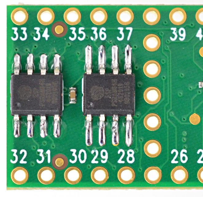
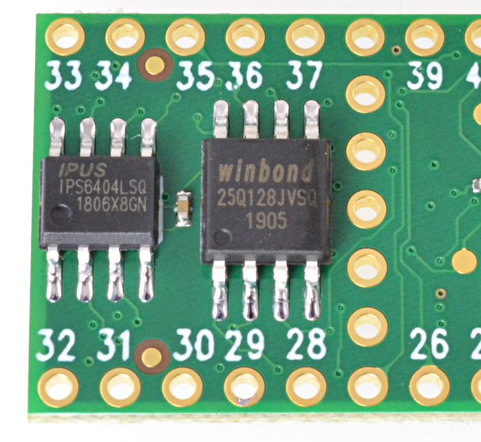
PSRAM is transparently accessible from program - variable just has to be prefixed with EXTMEM modifier:
EXTMEM char BIG_ARRAY[1000000];
Although, access to PSRAM should be much slower than embedded sram - due to serial interface.
USB Host is connector:
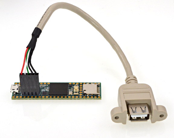
E.g. can drive external MIDI slave synthesizer.
W/o extra soldering, Teensy 4.1 provides SD card and USB host. On 4.0 it would require soldering to bottom SMT pins.
More digital and analog pins - easy to put several encoders and pots to design. Additional RAM (8 or 16 MB of PSRAM) is killer feature for synthesizer - allows good reverb implementation.
Teensy theremin project status
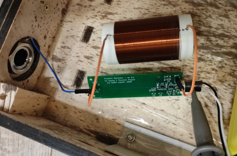
Got oscillator PCBs ordered from chinese manufacturer with 3 months delay (received by june). Yesterday, soldered two oscillator boards.
Soldering of small 74LVC2G04 logic footprints and 0805 SMD components is non-trivial experience.
Next steps:
test if oscillators are working
write theremin sensor lib with DMA writing captured positions of raising and falling edges of oscillator signals (150 to 250MHz precision)
collect sensor data to evaluate oscillator stability and noise level (especially main hum noise Dewster is talking about so much)
Main question to clarify - if Teensy 4.X hardware enough for implementing of good (precise low latency low noise) digital theremin sensor.
Now I have only Teensy 4.0 boards. It's enough for testing of sensor, but for final implementation it makes sense to use newer and powerful teensy 4.1 board. Going to order a few - with PSRAM chips and USB host cables.
Other components planned to use remain the same: teensy audio board (line in/out, phones out), S/PDIF transmitter module for digital audio out (optional), 3.2 inch 320x240 LCD with resistive touch - GUI + tuner / visual pitch preview -- everything is from teensy store (pjrc.com) except oscillator boards and some main board to connect parts together. Such design should be easy to reproduce for everyone.
Soldered two oscillators on 74LVC2G04
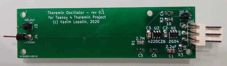
Simple schematic is used. Not sure how should such kind of oscillators be named. Colpitts?
One side of L is driven by inverter via 10 Ohm R. Other side is connected to antenna and to inverter input (via R=2Meg).
LTSpice model:
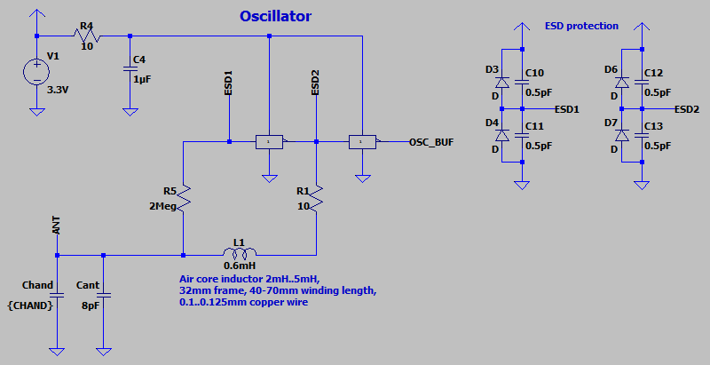
Simulation shows 130 VPP which should mean that it has high Q.
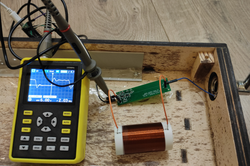
Connecting power, inductor, antenna, scope:
Powered on, working:
If oscillator pcb is placed inside inductor frame, working as well.
Hand far from antenna: frequency = 2.09MHz
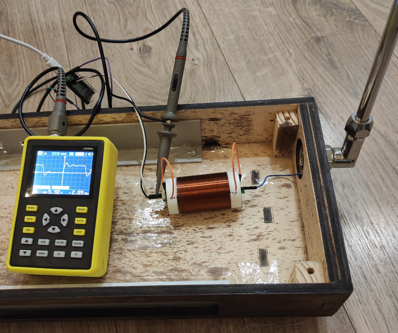
Hand close to antenna: frequency = 1.95MHz
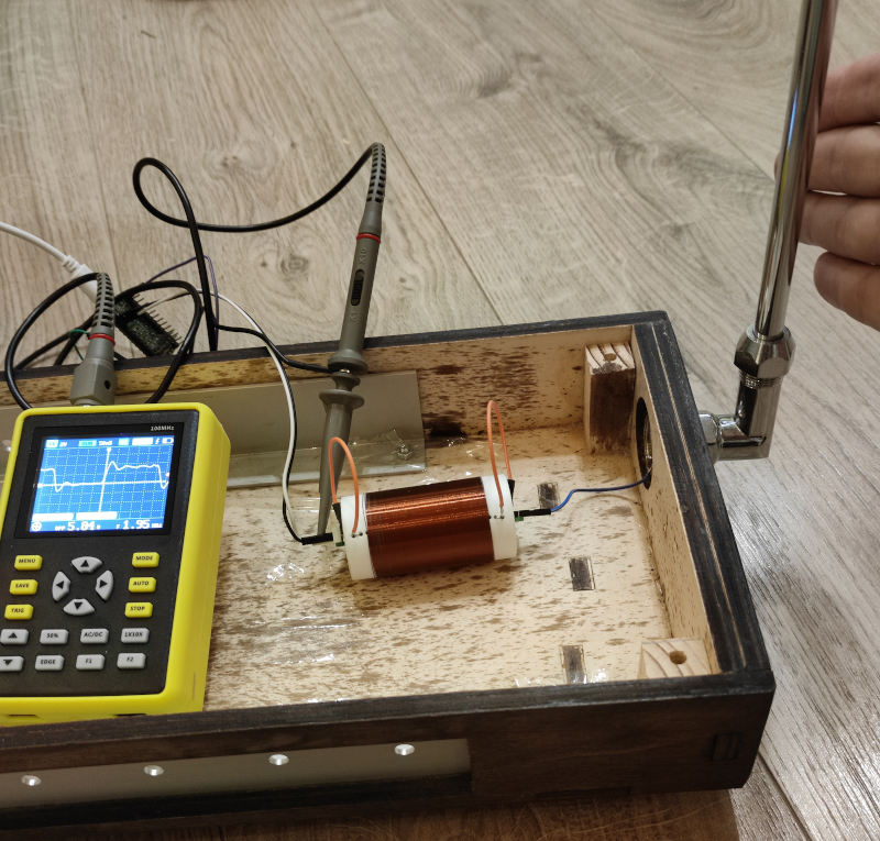
For hand distance 1-2cm, frequency = 2.00MHz
Issue found: when hand touches antenna, oscillation stops. (Actually, some high frequency low amp signal is visible on output, but it's possible due to cheap scope frequency limits).
It's not a good behavior for theremin. Trying to figure out how to keep oscillator working while touch.
Would decreasing of input R help? What about connecting capacitor between antenna and GND?
Next step: write test program for Teensy 4.0 to measure frequency and check oscillator stability and hum noise level.
Ordered Teensy 4.1, with 2*8MB PSRAM chips. Will retarget development to this board.
So far, going to use Teensy 4.0.
"Simple schematic is used. Not sure how should such kind of oscillators be named. Colpitts?" - Buggins
Seems more like Vackar. I'll have to simulate it, but I'm not seeing how you get 180 degrees through the LC? (180 degrees inverter + 180 degrees LC = 360 degrees = Barkhausen criteria.) Vackar uses RC at the drive side to get 90 degrees, LC gives 90 degrees, C divider on the sense side to knock the voltage swing down. RC on drive side is obviously frequency dependent, so you would have to tailor it to the oscillation frequency (i.e. the value of your coil and antenna and environment, which is why it's rather problematic). Maybe you're getting 90 degrees from the input resistor and the capacitance of the CMOS gate input? [EDIT] Yes, that seems like what's probably happening, and that works in my simulation.
"It's not a good behavior for theremin. Trying to figure out how to keep oscillator working while touch."
Insulate it? Helps with ESD too. They all poop out to some degree.
You might want to lift the coil up off the wood a bit, it's probably experiencing significant C. You antenna is connected to the wood? If so, you're losing some absolute sensitivity there too. I wish wood was more like plastic in terms of C, it's not the most ideal thing to build Theremin cabinetry out of.
Hi folks!
First of all sorry if this comment its far away from this interesting topic, these last post have spoken about ESD protection, that is why this comment
I have burned several Theremins based in FET oscillators by Electroestatical chokes, as you supposed touching antenna with with electrostatical charge. I have tried too fix this with a simple diode between antenna and air coil, but its very useless, i wonder to myself if ESD protection is a good improvment, or just it is a weakness of a Theremin based in FET oscillators...?, i just would like to know the use of ESD protection in Theremin device, thank you a lot
"I have burned several Theremins based in FET oscillators by Electroestatical chokes, as you supposed touching antenna with with electrostatical charge. I have tried too fix this with a simple diode between antenna and air coil, but its very useless, i wonder to myself if ESD protection is a good improvment, or just it is a weakness of a Theremin based in FET oscillators...?, i just would like to know the use of ESD protection in Theremin device, thank you a lot" - robonil
I don't know if FET oscillators in general are more prone to ESD, that could be the case. To know anything about ESD you have to test to failure, and I don't know of any Theremin designers do that. Few even take basic steps to mitigate ESD. There are low capacitance ESD clamps on the market for antennas and logic and such, you might look into those. The first line of defense though is insulating the antennas.
"The only Theremin with "visible" ESD protection I am aware of, is the Russian tVox tour Theremin. To protect the FETs on the pitch side and the CMOS circuitry on the volume side, there are EPCOS M51-C90X surge arresters on both sides." - Thierry
Ah, fascinating stuff Thierry, thanks!
All the specs seem good for Theremin use, but they conduct at 90V, which seems rather high?
These surge arresters are placed in the circuit in places where you find between 60 and 90Vpp signals. Thus they don’t have an impact on the signal, that’s important. These high voltage signals (due to LC resonance) are later divided down by the corresponding RLC circuitry of the oscillators and detectors to their nominal 3.3 to 5Vpp. An electrostatic discharge (limited to 90V by the surge arrester) would, after the same voltage division, fall in the tolerable input range of the FETs and HCMOS ICs.
That’s the theory. In practice, you can’t predict what will exactly happen with a single ESD. Thus, you can’t protect a theremin circuit at 100%. You can just greatly reduce the statistical risk. Afterwards, there might always be someone with rubber soles, wearing a wool pullover, touching an antenna after petting a cat...
You must be logged in to post a reply. Please log in or register for a new account.


