Teensy 4.0 600MHz ARM Cortex M-7 MCU - ideal for digital MCU based theremin?

Posted: 10/2/2020 2:36:38 PM
Buggins

From: Porto, Portugal

Joined: 3/16/2017


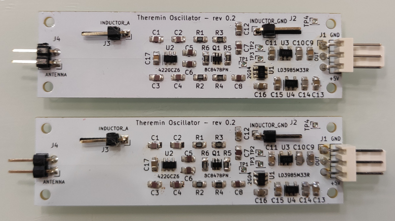
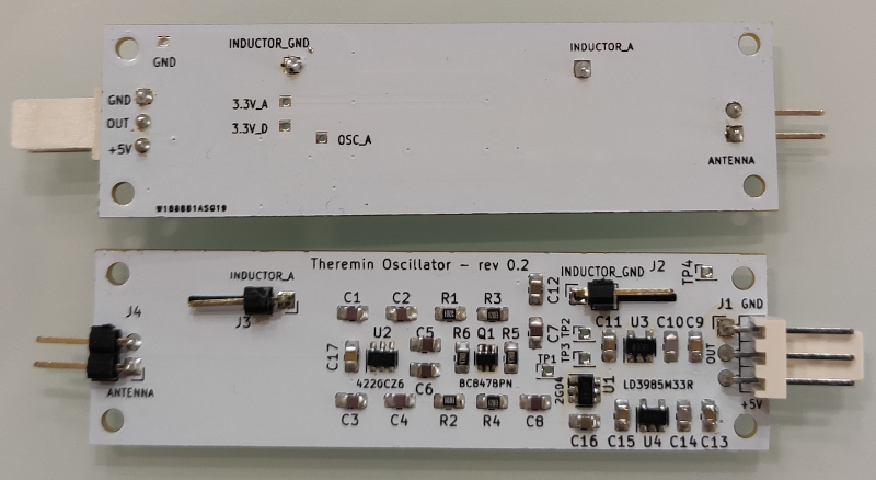
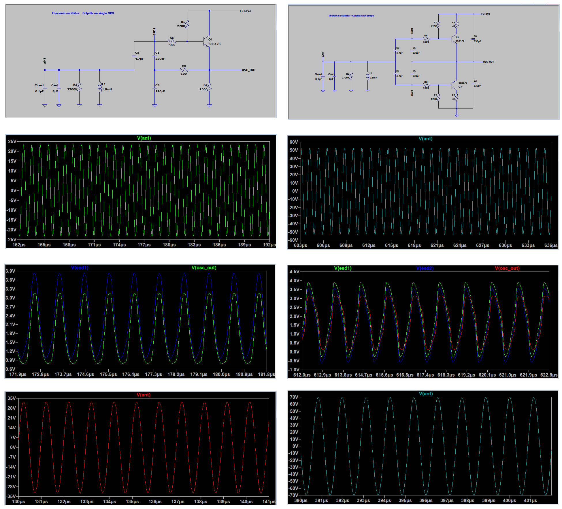
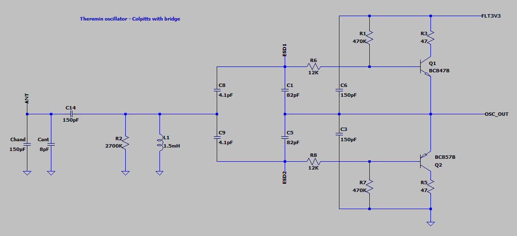
While oscillator boards are traveling from china, I'm planning the rest of Teensy4.1 based Theremin design.


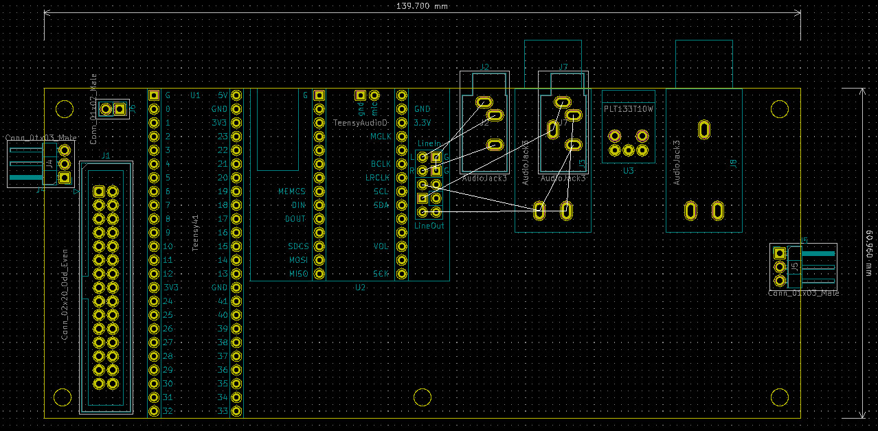
There will be two PCBs - main and display/control. Display board will be mounted under optimal angle for viewing.


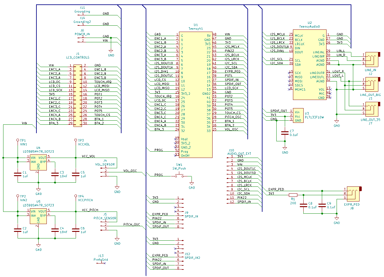
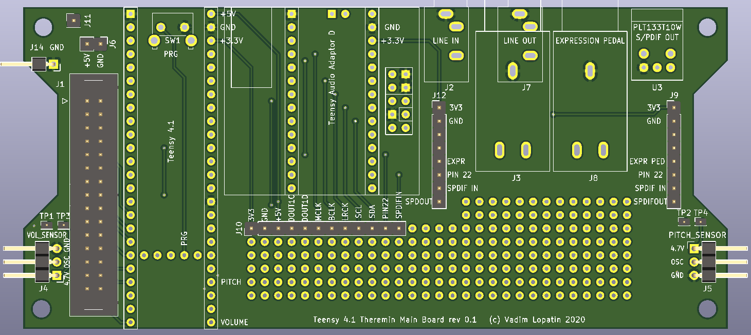
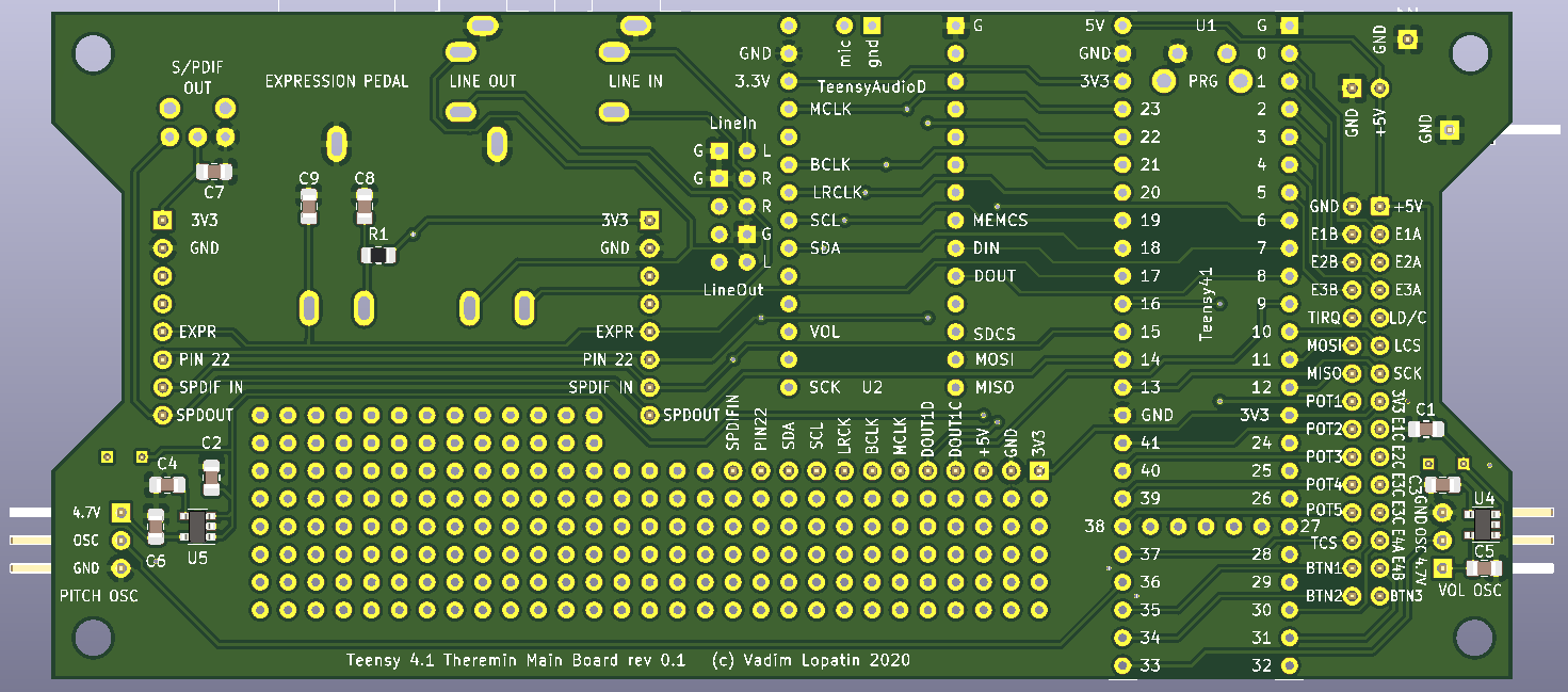
On main board, Teensy4.1 MCU and AudioAdaptor revision D are connected using pin headers.

Micro USB connector located on Teensy4.1 - for power, programming, connectivity (USB slave for Serial port and MIDI).

Phones out is located on audio adaptor board.

Line In - 3.5mm jack

Line Out - 6.35 or 3.5mm jack

S/PDIF optical out

Expression pedal 6.35mm jack (for connection of POT pedal)

Power DC In barrel socket can be mounted on rear panel and connected using 2 pins.

Grounding connector: can be mounted on rear panel and connected to gnd pin.

SDCard interface: on front panel - soldered on Teensy4.1

Optional USB Host, panel mounting, connected with cable.

Optional Ethernet, panel mounting, connected with cable.

30pin IDC connector - for connecting display/controls board.


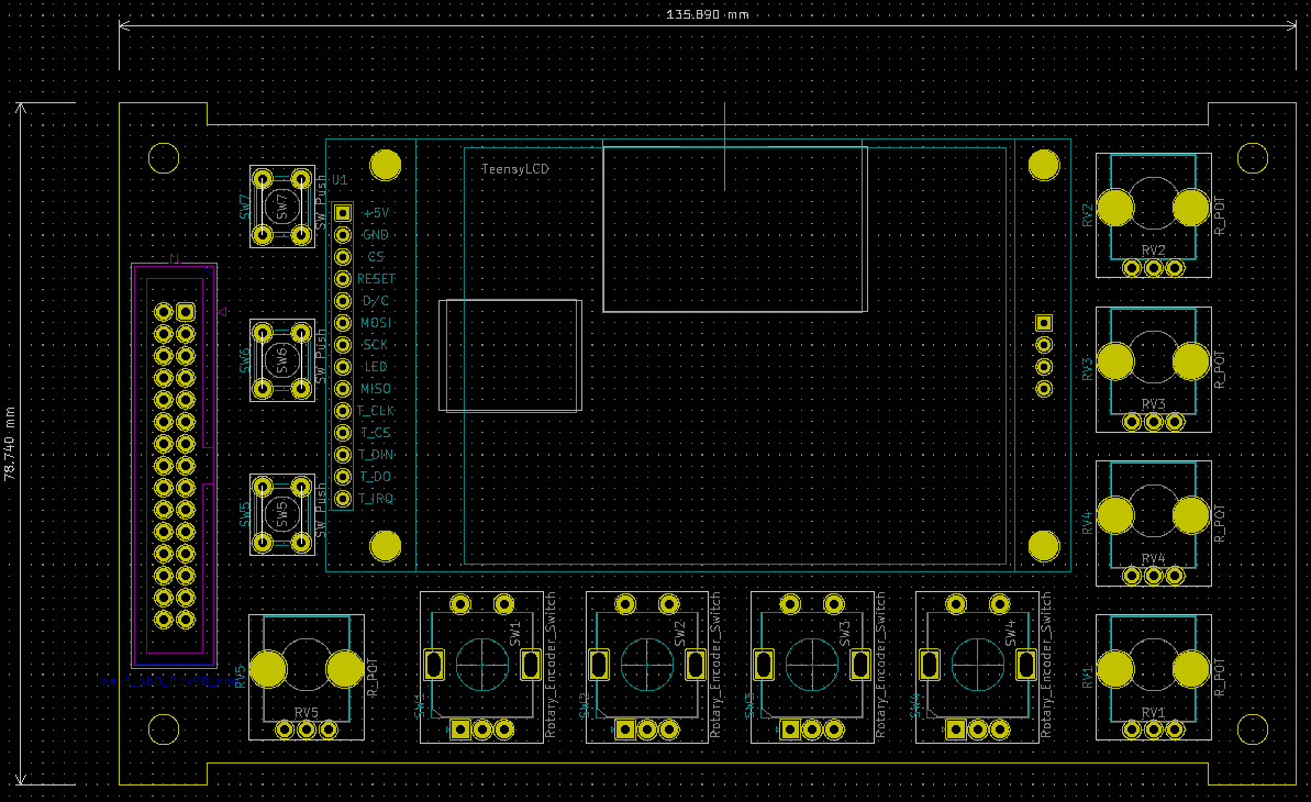
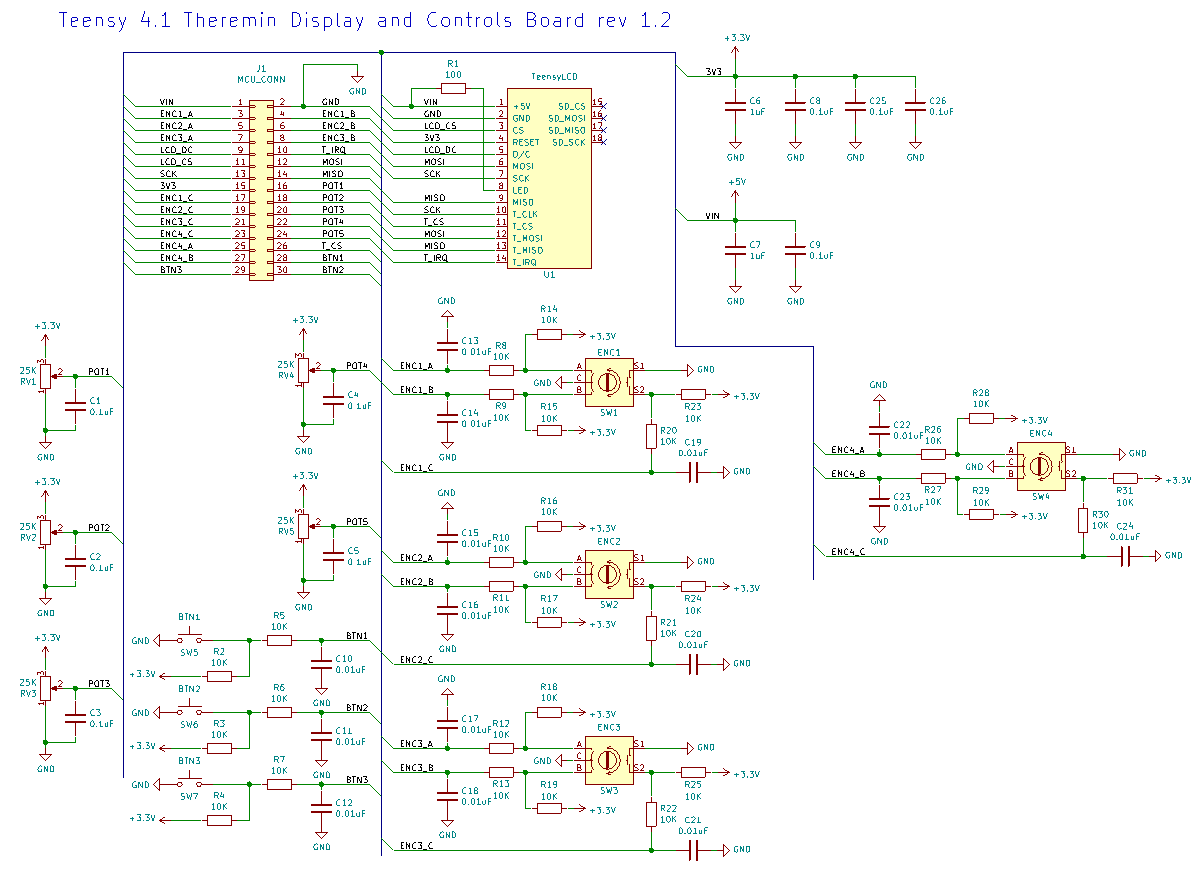
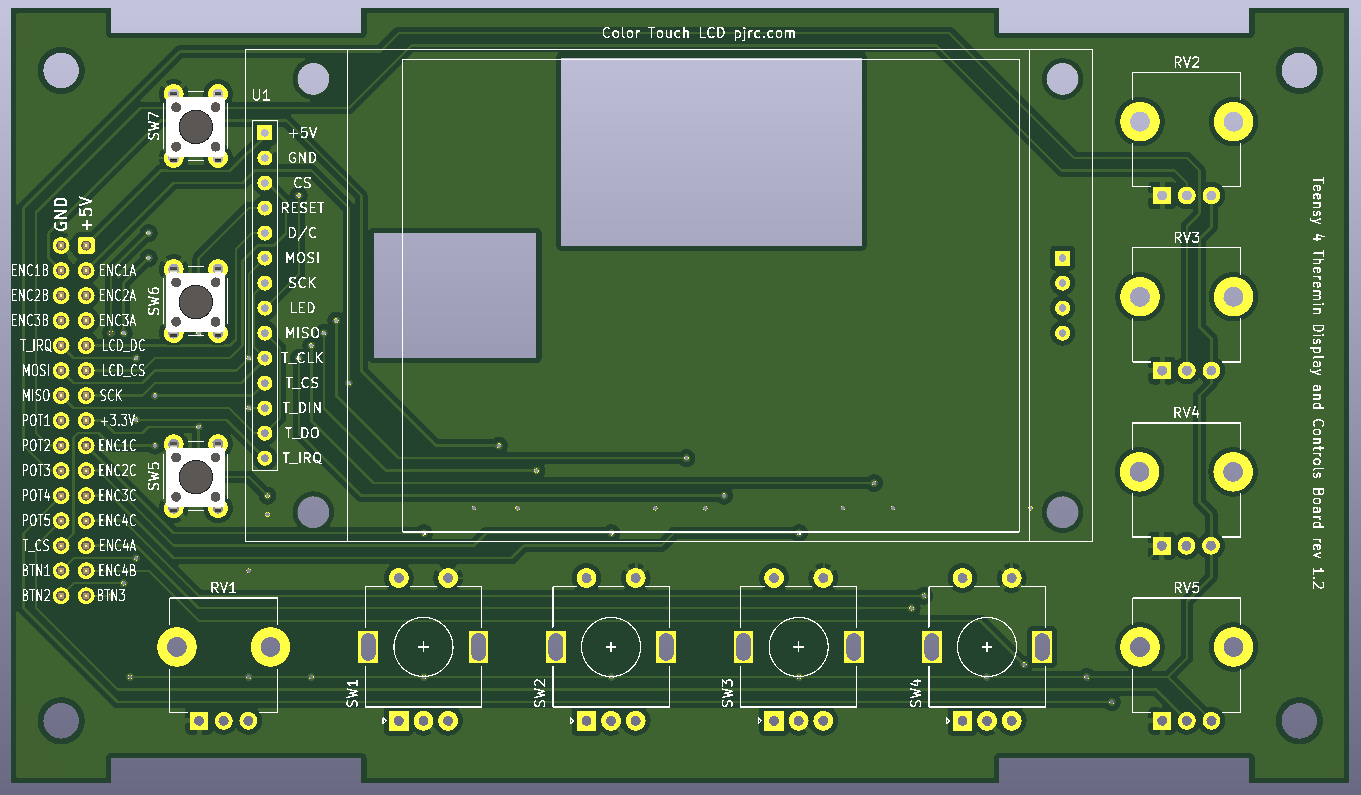
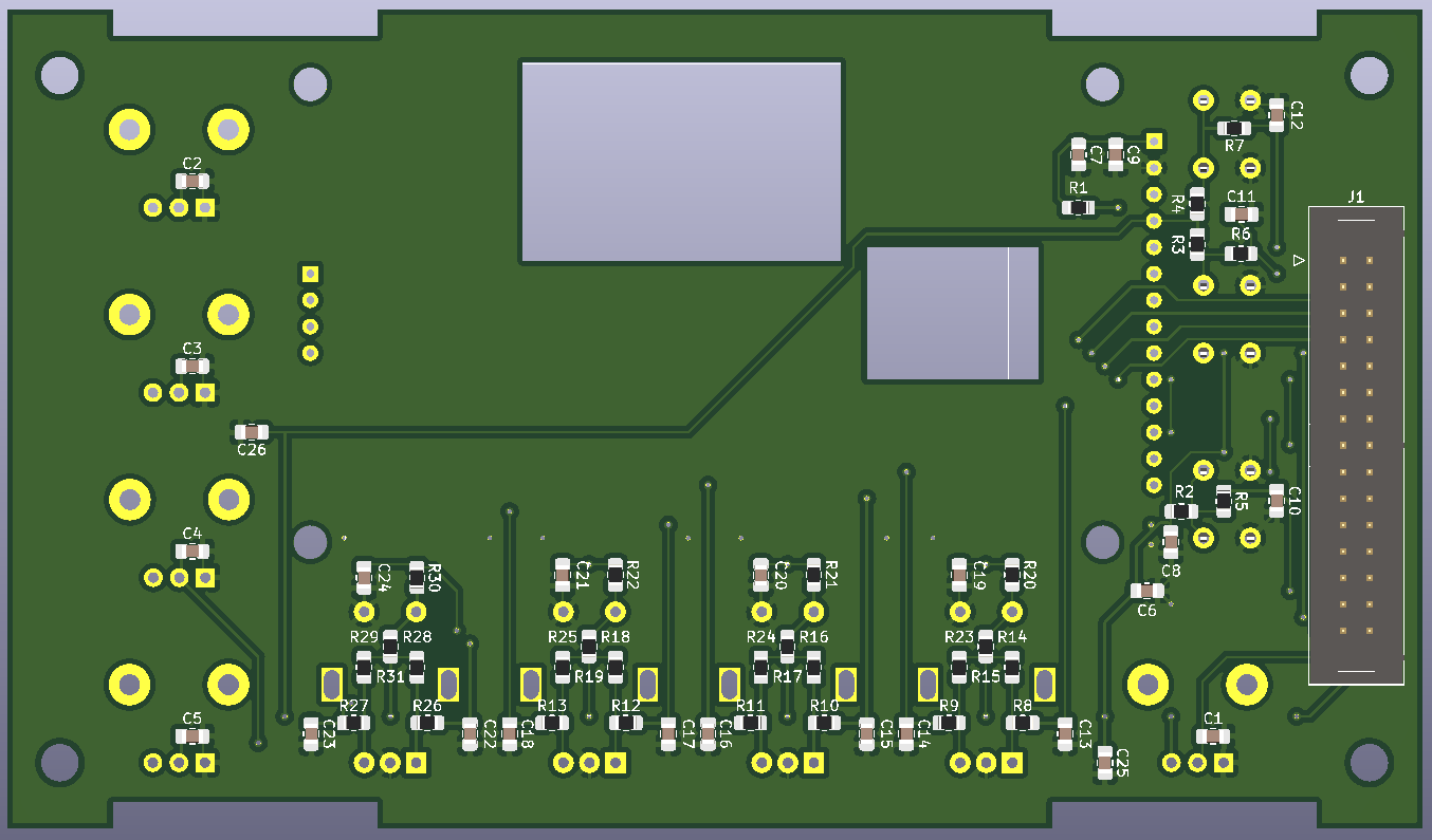
Designing LCD screen and controls board.

LCD is 2.8 inch 320x240 screen with SPI ILI9341 controller and resistive touch (SPI XPT2046).

I'm not sure what controls are required, so trying to place reasonable amount of different controls.

iMXRT1060 has 4 hardware rotary encoder support modules with internal debouncing. So it makes sense to use 4 encoders.

There are a lot of analog input pins available, so putting as many pots as possible (5 pots fit ok).

Several buttons may be useful (mute, calibrate, other functions). 3 or 4 may fit on left side.

30pin IDC connector additionally limits number of controls.


Posted: 10/6/2020 8:35:10 PM
Buggins

From: Porto, Portugal

Joined: 3/16/2017

Routed Teensy4.1 Theremin main board in KiCAD.

Schematics:


Micro USB on Teensy board - usb slave: power, serial console, MIDI
Phones Out - 3.5mm jack
Line In - small 3.5mm jack
Line Out - small 3.5mm or big 6.35mm jack
S/PDIF OUT - optical transmitter
Expression Pedal - to control some synthesizer parameter
MicroSD card on Teensy board - 4wire interface
16MB PSRAM will be soldered on Teensy board
LCD/Controls 30-pin IDC header: 320x240 LCD with resistive touch, 4 encoders with buttons, 5 pots, 3 buttons
USB host cable with panel mounting - optional
Power In barrel jack DC +5V is optional
Program button
Grounding connector - panel mounting


Oscillator connectors have separate voltage regulators 4.7V.

Top view:


Bottom view:


Almost all pins utilized. 4 pins left unused on main board. Reserved for future extensions.

For future extensions, some signals routed to headers. Prototyping area.

2 of unused pins can be used as I2S stereo data output signals, or just for buttons (e.g. pedal buttons)

1 unused pin can be used for S/PDIF IN or ADC (e.g. for additional expression pedal).

1 unused pin is just a GPIO with ADC capabilities


Posted: 10/12/2020 12:54:29 PM
Buggins

From: Porto, Portugal

Joined: 3/16/2017

Just received new oscillator (symmetric npn+pnp colpitts) PCBs. Soldering...

BC847BPN SOT363 is really hard to solder.

Posted: 10/13/2020 1:20:57 PM
Buggins

From: Porto, Portugal

Joined: 3/16/2017

Finally I've soldered new oscillator boards for Teensy 4 Theremin project.

Features:
* symmetric dual colpitts schematic on NPN + PNP transistors
* two onboard voltage regulators - separate for analog and digital parts
* input power DC +3.6..6V, digital output 3.3V
* ESD protection IC


Test setup:

For measuring theremin sensor performance, I'm using simple sketch for Teensy4, capturing oscillator signal edge positions,
applying pre-filtering, storing output once per 1ms, for 15seconds, then dumping 15000 measured values to serial console.
Copy+paste of serial console to Excel spreadsheet allows doing signal analysis.

New data is available on pages "NPN PNP noise" and "NPN PNP movement" in spreadsheet.

First experiment: hand movement from far distance to antenna, then to shoulder, then forward to ~50cm distance, short vibrato, back to 60cm, vibrato.

Raw captured data. Good at first sight (although far range movement is mostly invisible), but really it's noisy.


Together with linear hand position, noise becomes visible after converting of data to log scale:


Most of noise is main hum.

Adding 20ms (20 samples) moving average filter to filter out 50Hz signal cleans the data very well.


To see noise level and oscillator stability, I've captured data w/o hand nearby (I'm sitting one meter from antenna, trying not to move).

After 20ms filter and log scaling (using the same Y axis range as for hand movement) we see almost horizontal line.


Zooming in shows that there is still a visible noise.


I believe on practical playing distance, noise level in detected hand position value will be below audible values or just averaged out during the synthesis.

Conclusion: proposed oscillator schematic + Teensy4 MCU digital theremin sensor is good enough for practical usage.
Let's go further and design the rest of hardware: main board and display/controls board.


Posted: 10/14/2020 1:45:01 AM
dewster

From: Northern NJ, USA

Joined: 2/17/2012

Vadim your boards are really nice looking!  I appreciate the data too! 

How does the NPN+PNP oscillator noise level (after mains filtering via 20ms sampling) compare to a single NPN oscillator?  Is the voltage swing at the antenna larger / smaller?

How is KiCad working out for you?

Posted: 10/14/2020 4:22:08 PM
Buggins

From: Porto, Portugal

Joined: 3/16/2017


How does the NPN+PNP oscillator noise level (after mains filtering via 20ms sampling) compare to a single NPN oscillator? 

TBD. Will check a bit later.

Is the voltage swing at the antenna larger / smaller?


Antenna swing is twice bigger. Oscillation starts faster.

Comparision of single NPN (left) and NPN+PNP bridged (right) colpitts oscillators in LTSpice model.

Line 1: schematics - ltspice model  NPN model download link, NPN+PNP download link


Initial parameters: R_loss 2700K, L series R = 82

Line 2: antenna voltage swing

Line 3: signals on amp input(s) and output

Line 4: antenna swing after changing of L series R to 32 Ohm


Trying different simulation with different parameters:

R_loss 470K, L series R = 32: antenna swing NPN+PNP 60Vpp, NPN 13.5Vpp and slow start
R_loss 1000K, L series R = 82: antenna swing NPN+PNP 80Vpp, NPN 28Vpp


One issue I see with NPN+PNP on real hardware. Oscillation stops on touching of antenna. Although model with 470K "loss" R oscillates ok.
I hope it can be fixed by changing of some component values.


How is KiCad working out for you?


It takes several days to learn KiCAD UI and its differences from other EDAs.

Now I'm pretty satisfied by KiCAD. It suits very good at least for my projects.

Some components are missing in standard library (e.g. ESD ICs, 6.35mm audio jack...).
But it's easy to create your own symbol and footprint.
I'm always using manual placement and routing. Not sure how it works in KiCAD (if there is any).

Today, I've finished routing of Display/Controls board and ordered manufacturing of Main board and Display controls board (5 + 5 pcs, $63 with delivery).

Display/Controls board in KiCAD:


Posted: 10/14/2020 9:04:11 PM
Thierry

From: Colmar, France

Joined: 12/31/2007

Put a 150pF capacitor in series with the antenna. When touching, there will be another 150pF from the human body which makes an effective capacitance of 75pF and the ohmic resistance of the body is decoupled. Then, you only need to stabilise the oscillator in the simulation for a C_hand max of 150pF. ;-) 

Posted: 10/15/2020 4:23:56 PM
Buggins

From: Porto, Portugal

Joined: 3/16/2017


m the human body which makes an effective capacitance of 75pF and the ohmic resistance of the body is decoupled. Then, you only need to stabilise the oscillator in the simulation for a C_hand max of 150pF. ;-)
- Thierry

Played a bit with LTSpice simulation (link to model).
Added decoupling C 150pF before antenna. L=1.5mH with R_series=40
Tried to maximize sensitivity of working range (F_chand_0pF - F_chand_1.5pF)/F_chand_0pF ~ 3.7%
while maximizing antenna swing (~90Vpp)
and stable oscillation with C_hand = 150pF and R2(R_loss) = 1000Megs

Is R_loss (LC tank energy loss) required in model to simulate hand touching antenna with c_hand=150pF, or it can be increased?
I've managed to get oscillation working with C_hand=150pF and R_loss=470K, but only with a bit reduced sensitivity (2.5..3%) and antenna voltage swing.

Extreme voltage swing on antenna 200..220Vpp can be achieved only with reduced sensitivity and stopping of oscillation on touch.
Voltage swing and touch tolerance can be as well improved by decreasing of inductor series resistance.

Does someone try to use ferrite core inductors? Such inductors can provide higher Q and extremely low R_series.
Are they really have problems with stability? Etherwave has coils with ferrite core for trimming of L, and it's working well.

So far, I seen the only one issue bridged schematic of oscillator introduces comparing to single npn colpitts.
It's connected to LC tank in two points and hence adds twice bigger C which reduces sensitivity.

How does the NPN+PNP oscillator noise level (after mains filtering via 20ms sampling) compare to a single NPN oscillator?

-- dewster


Some results for noise measurement (15000 items raw data samples one per 1ms) collected using single NPN oscillator, with me sitting far from antenna.

Collected data appended to spreadsheet.

Metric: relative difference between max and min from data after 20ms moving average filter:  (max-min)/max
For NPN+PNP test, this metric is 0.00000628, while for NPN-only it's 0.000110931
From these metrics, NPN+PNP oscillator looks 17.5 times more stable and less noisy than NPN only oscillator.
Inductor is the same for both experiments.

Raw data:

Log scale filtered:


Strange changes in frequency are visible. Instability of oscillator?

Actually, comparision is a bit not fair.

NPN+PNP oscillator outputs signal directly using inverter buffer. Software filter on MCU eliminates signal duty cycle modulations by calculating centers of pulses.
NPN oscillator has D flipflop on its output dividing oscillator frequency by 2. Duty cycle compensation does not work in this case.

As well, NPN oscillator doesn't have on-board voltage regulators. Only RC filter on power line. Powered by 3.3V from MCU. NPN+PNP board has separate 3.3V voltage regulators for analog and digital parts.


Posted: 10/15/2020 6:12:01 PM
dewster

From: Northern NJ, USA

Joined: 2/17/2012

"Is R_loss (LC tank energy loss) required in model to simulate hand touching antenna with c_hand=150pF, or it can be increased?"  - Buggins

It's there to make the simulation behave more like the real circuit.  It models RF loss (I think) and gives perfect sim coils and capacitors a way to wind down, otherwise any startup perturbations can ring on for a really long time and look like steady oscillation when they're not.  It's not there to simulate touching the antenna.  Set it to whatever comes closest to whatever your real circuit is doing, voltage swing-wise.  The resistor also helps to differentiate oscillators that will work in real life from those that will only work in simulation.

"I've managed to get oscillation working with C_hand=150pF and R_loss=470K, but only with a bit reduced sensitivity (2.5..3%) and antenna voltage swing.
Extreme voltage swing on antenna 200..220Vpp can be achieved only with reduced sensitivity and stopping of oscillation on touch."

Rather than trying to get the oscillator to keep going through touch, why not just insulate it?  Could be your first line of defense against ESD too.  My oscillator gets a little weird when you touch the raw plate, and I don't consider that to be a valid operating mode for it.

"Voltage swing and touch tolerance can be as well improved by decreasing of inductor series resistance.
Does someone try to use ferrite core inductors? Such inductors can provide higher Q and extremely low R_series.
Are they really have problems with stability? Etherwave has coils with ferrite core for trimming of L, and it's working well."

It's been my experience that well designed and constructed air cores will always have higher Q than ferrite, particularly at resonance.  The wire resistance losses are smaller than the ferrite magnetization losses.  Strangely, wire resistance losses are almost meaningless in this application: I've made air core coils out of very thin wire and somewhat thicker wire, and the wire diameter doesn't have any effect that I can see on voltage swing.  This was a big surprise for me.

"So far, I seen the only one issue bridged schematic of oscillator introduces comparing to single npn colpitts.
It's connected to LC tank in two points and hence adds twice bigger C which reduces sensitivity."

Anything that cuts into your SNR margins is a worry, because the Theremin antenna and case construction can bring other compromises in this regard.

"As well, NPN oscillator doesn't have on-board voltage regulators. Only RC filter on power line. Powered by 3.3V from MCU. NPN+PNP board has separate 3.3V voltage regulators for analog and digital parts."

Yeah, that doesn't seem like an apples to apples comparison.  Voltage stability is usually quite critical to oscillator stability.

Posted: 10/16/2020 4:29:36 AM
Buggins

From: Porto, Portugal

Joined: 3/16/2017


"Is R_loss (LC tank energy loss) required in model to simulate hand touching antenna with c_hand=150pF, or it can be increased?"  - Buggins

It's there to make the simulation behave more like the real circuit.  It models RF loss (I think) and gives perfect sim coils and capacitors a way to wind down, otherwise any startup perturbations can ring on for a really long time and look like steady oscillation when they're not.  It's not there to simulate touching the antenna.  Set it to whatever comes closest to whatever your real circuit is doing, voltage swing-wise.  The resistor also helps to differentiate oscillators that will work in real life from those that will only work in simulation.
--dewster

Ok. I'll use R_loss = 2.7Megs for all simulations.
Hand touch will be simulated as 150pF C_hand.


"I've managed to get oscillation working with C_hand=150pF and R_loss=470K, but only with a bit reduced sensitivity (2.5..3%) and antenna voltage swing.
Extreme voltage swing on antenna 200..220Vpp can be achieved only with reduced sensitivity and stopping of oscillation on touch."

Rather than trying to get the oscillator to keep going through touch, why not just insulate it?  Could be your first line of defense against ESD too.  My oscillator gets a little weird when you touch the raw plate, and I don't consider that to be a valid operating mode for it.
--dewster

I just want to have the ability to detect such condition. For volume antenna, touch or double touch can toggle mute. For pitch, it should continue to use highest (last detectedd) pitch.
Stopping of oscillation can be detected as touch as well. But I'm not sure if recovering of oscillation at end of touch will not cause any side effects.


"Voltage swing and touch tolerance can be as well improved by decreasing of inductor series resistance.
Does someone try to use ferrite core inductors? Such inductors can provide higher Q and extremely low R_series.
Are they really have problems with stability? Etherwave has coils with ferrite core for trimming of L, and it's working well."

It's been my experience that well designed and constructed air cores will always have higher Q than ferrite, particularly at resonance.  The wire resistance losses are smaller than the ferrite magnetization losses.  Strangely, wire resistance losses are almost meaningless in this application: I've made air core coils out of very thin wire and somewhat thicker wire, and the wire diameter doesn't have any effect that I can see on voltage swing.  This was a big surprise for me.
--dewster

I have 0.1, 0.125, 0.2, 0.3 copper wires. I believe it makes sense because L is decreased by 0.25 while R is decreased by 1.5


"So far, I seen the only one issue bridged schematic of oscillator introduces comparing to single npn colpitts.
It's connected to LC tank in two points and hence adds twice bigger C which reduces sensitivity."

Anything that cuts into your SNR margins is a worry, because the Theremin antenna and case construction can bring other compromises in this regard.
--dewster

Will try to reduce C between LC tank and amplifier a bit more.


"As well, NPN oscillator doesn't have on-board voltage regulators. Only RC filter on power line. Powered by 3.3V from MCU. NPN+PNP board has separate 3.3V voltage regulators for analog and digital parts."

Yeah, that doesn't seem like an apples to apples comparison.  Voltage stability is usually quite critical to oscillator stability.
--dewster

Solution is to use the same PCB and even the same NPN+PNP transistor. Some wires should be cut and some components not soldered to exclude PNP part.
This will guarantee fair play - same transistor and same regulators will be used for comparision.

Minimal C introduced by amplifier is limited by transistor base current.
Did someone try using NMOS in oscillator? Any disadvantages except sensitivity to ESD?
Can believe MOS should give smaller input current and allow smaller C (I think 1pF is good goal).
Can bridged NMOS + PMOS schematic provide better results?


I believe a big portion of noise comes from digital signal edges.
It applies even to your phase detection approach.
If averaging still gives enough bits, does it make sense to reduce frequency of oscillator by increasing of L?
Twice less edges - twice less noise from edges.

If we could produce clean sine wave signals from oscillator, 2 or 4 shifted by PI/2, then put it to fast ADC (single ended for 2 signals, or differential for 4 signals), precise frequency measure of oscillator becomes possible.
For PI/2 shifted pair, atan2(sample1, sample2) can be used for getting phase value. Averaging of phase measures sequence may filter out a lot of noise and provide enough number of bits.
4 wire 2 differencial pairs should reduce noise from oscillator to ADC line.
This approach is possible for FPGA with fast ADC (e.g. 100MSPS).


You must be logged in to post a reply. Please log in or register for a new account.