Teensy 4.0 600MHz ARM Cortex M-7 MCU - ideal for digital MCU based theremin?

Posted: 10/16/2020 11:59:06 AM
dewster

From: Northern NJ, USA

Joined: 2/17/2012

"I just want to have the ability to detect such condition. For volume antenna, touch or double touch can toggle mute. For pitch, it should continue to use highest (last detectedd) pitch.  Stopping of oscillation can be detected as touch as well. But I'm not sure if recovering of oscillation at end of touch will not cause any side effects." - Buggins

If you have a volume axis polarity option that lets the user pick closer=louder, then muting via antenna touch would require them to play a loud note in order to mute, which would be weird.  Accidental touch of volume could mute during performance.  And encouraging the user to stop the oscillator is kind of asking for it IMO.  There are plenty of ways to positively mute / unmute, and I'd pick one with the fewest opportunities to wreak havoc, preferably something mechanically positive, and not a touch switch or anything that brushing against could easily toggle.

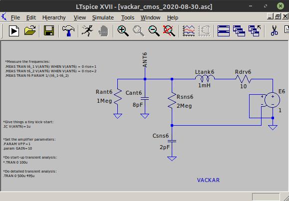
"Will try to reduce C between LC tank and amplifier a bit more."

"Can believe MOS should give smaller input current and allow smaller C (I think 1pF is good goal)."

The problem with these types of oscillators is that the coupling capacitor works both ways, so reducing it to increase absolute sensitivity gives a double whammy by reducing both sense and drive, wussiness squared.

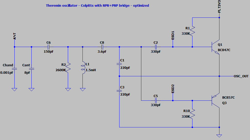
"Solution is to use the same PCB and even the same NPN+PNP transistor. Some wires should be cut and some components not soldered to exclude PNP part.
This will guarantee fair play - same transistor and same regulators will be used for comparision."

I was thinking the same thing!

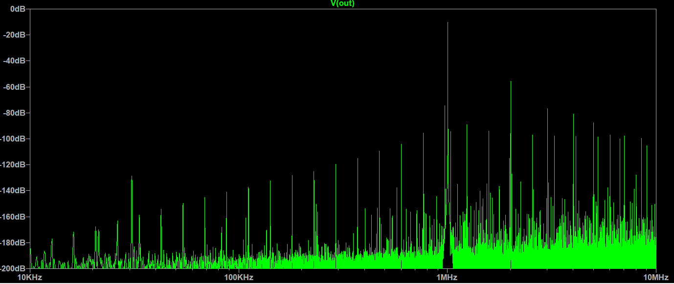
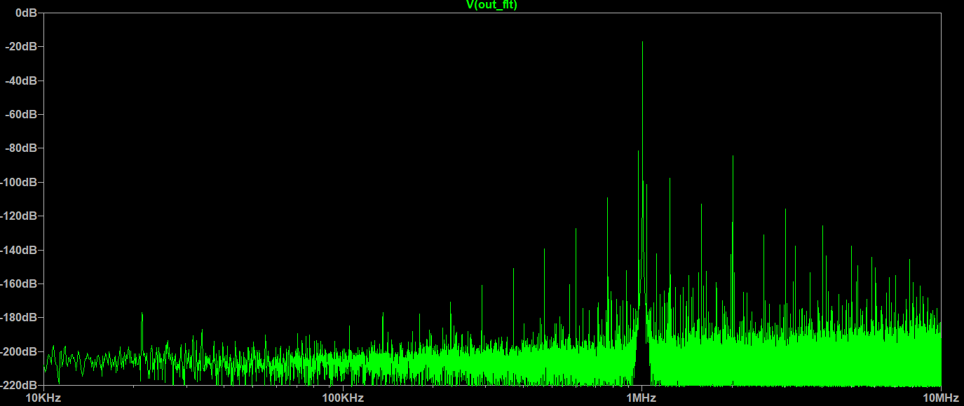
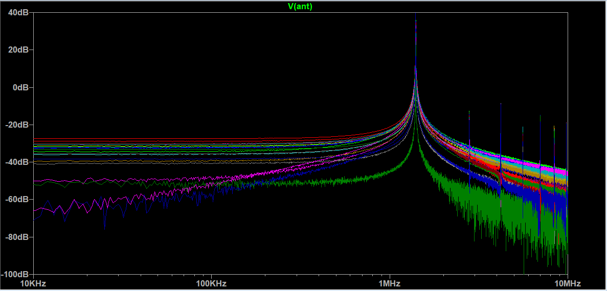
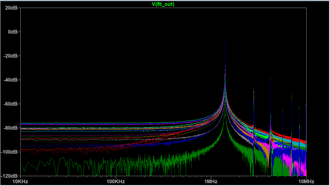
"I believe a big portion of noise comes from digital signal edges.
It applies even to your phase detection approach.
If averaging still gives enough bits, does it make sense to reduce frequency of oscillator by increasing of L?
Twice less edges - twice less noise from edges."

True, each measurement introduces noise, so noise goes up directly with measurements, but averages down by the square root of measurements (if we are limited to simple averaging).  But you can't filter out aliasing, which is anything above 1/2 the sample rate (LC oscillation frequency).  Most noise is mains hum, but it's something to think about.

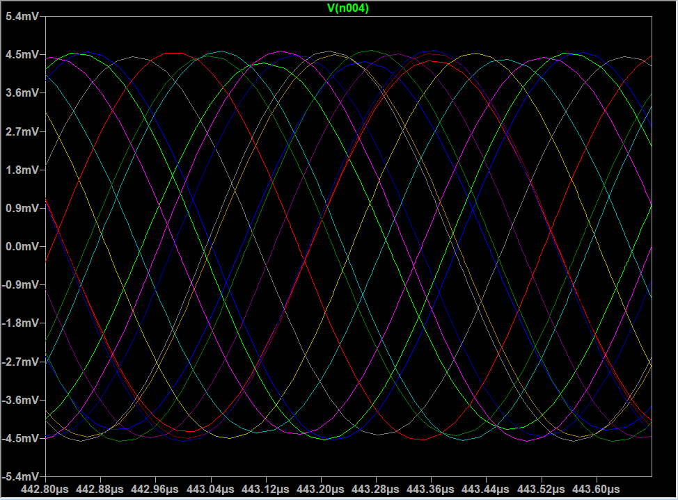
"If we could produce clean sine wave signals from oscillator, 2 or 4 shifted by PI/2, then put it to fast ADC (single ended for 2 signals, or differential for 4 signals), precise frequency measure of oscillator becomes possible.
For PI/2 shifted pair, atan2(sample1, sample2) can be used for getting phase value. Averaging of phase measures sequence may filter out a lot of noise and provide enough number of bits.
4 wire 2 differencial pairs should reduce noise from oscillator to ADC line.
This approach is possible for FPGA with fast ADC (e.g. 100MSPS)."

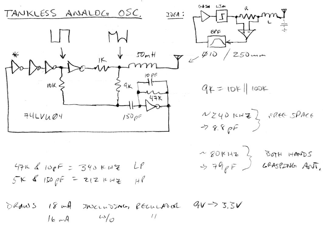
I agree, and then you would be truly sampling without squaring things up (a non-linear process), which would take anti-aliasing up to 50MSPS in your example, rather than LC freq/2.  And driving the tank with a sine wave would eliminate injected harmonics and the need for dither.  That would be a perfect world.

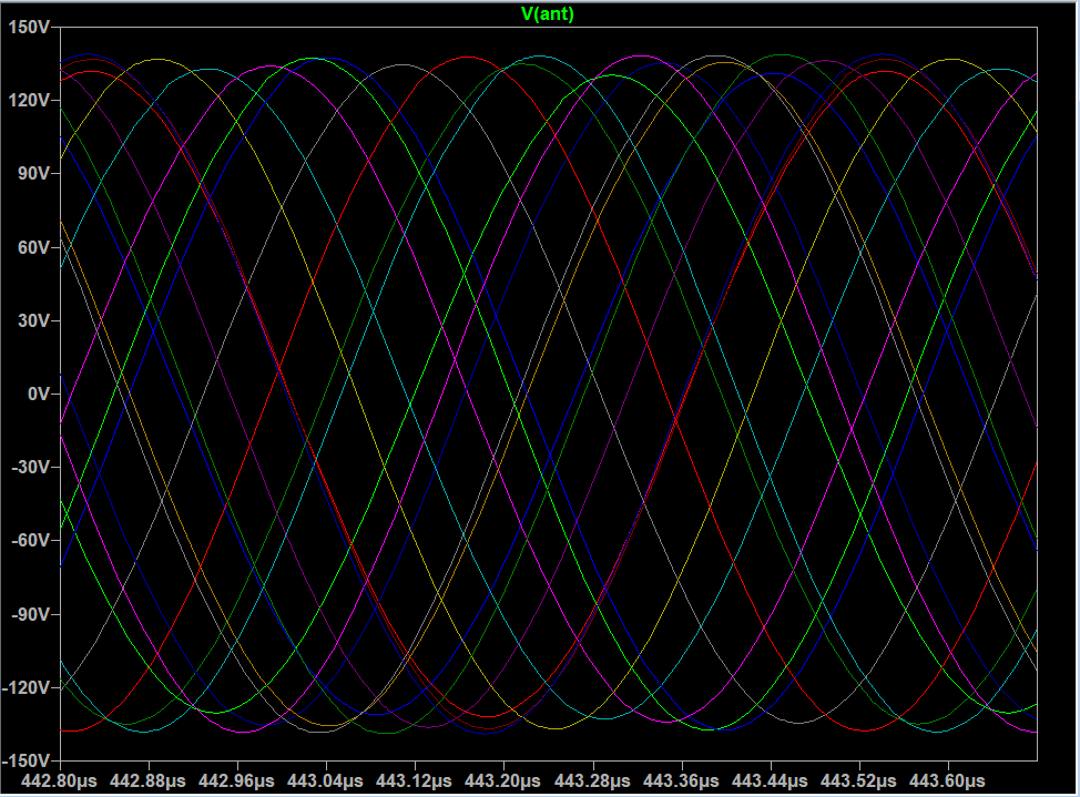
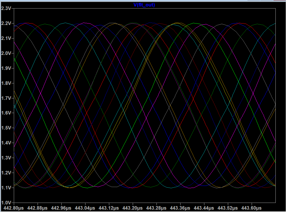
My DPLL approach at least drives with a small square wave into high Q LC with no phase error, which gives a really nice big ~pure sine wave at the antenna.  And the sensing edges are 90 degrees from the driving edges, which gives things time to settle.  The squaring has analog DC balance (inverter R feedback), but the DPLL itself can work with somewhat imperfect duty cycles.  You have to pick your battles with this stuff and do the best you can with what you have (the whole reason for your project :-).  The general environment and emissions from your own circuitry can work against you at every step, and stuff inevitably happens when measuring femto-Farads in real-time.

Posted: 10/16/2020 5:19:42 PM
Buggins

From: Porto, Portugal

Joined: 3/16/2017


If you have a volume axis polarity option that lets the user pick closer=louder, then muting via antenna touch would require them to play a loud note in order to mute, which would be weird.  Accidental touch of volume could mute during performance.  And encouraging the user to stop the oscillator is kind of asking for it IMO.  There are plenty of ways to positively mute / unmute, and I'd pick one with the fewest opportunities to wreak havoc, preferably something mechanically positive, and not a touch switch or anything that brushing against could easily toggle.
-- dewster

I really like this approach. I think it's more natural and intuitive way to control volume than classic one.
E.g. having fast / aggressive attack is more important than decay. It's easier to lower hand or finger than raise it.
As well this gesture is similar to pressing a key.


I've tried to implement JFET based oscillator in LTSpice.
It's working, but even bridged schematics gives bad sensitivity and low antenna voltage.

Then I've returned to NPN+PNP brided approach trying to maximize sensitivity.
Epic win! I've found how to make bridged oscillator with the same sensitivity (same C between amp and LC) as in single NPN schematics.
Now I don't see any disadvantages in this schematics comparing to single NPN approach. Does is still make sense to test single NPN noise?


Powered from 3.3V, it gives 4.5..5% of sensitivity, 70..120Vpp of antenna swing.
Tuning of component values allows to keep oscillating with C_hand=150pF, but C between amp and LC needs to be increased to 10pF which reduces sensitivity to 3.5..4%

LTSpice model to play with: link


Does it make sense to drive oscillator at higher voltage?

E.g. changing from 3.3V to 4.5V gives 35% higher antenna voltage swing.


Posted: 10/16/2020 8:28:44 PM
dewster

From: Northern NJ, USA

Joined: 2/17/2012

"I really like this approach. I think it's more natural and intuitive way to control volume than classic one.
E.g. having fast / aggressive attack is more important than decay. It's easier to lower hand or finger than raise it.
As well this gesture is similar to pressing a key."  - Buggins

I prefer it, I think it's more intuitive, and it makes percussive voices much easier to play.  But there is a gesture almost universally used by Thereminists where when changing notes they do a quick dip towards the antenna and a slow retract, on the beat, to shape the volume like that of an opera singer.  That is a bit counter-intuitive to do when the volume sense is reversed.

"I've tried to implement JFET based oscillator in LTSpice.
It's working, but even bridged schematics gives bad sensitivity and low antenna voltage."

JFETs have terrible gain, particularly at low voltage, which makes them bad candidates here.  You want a somewhat snappy response to a small input.

"Does is still make sense to test single NPN noise?"

You should prove yourself wrong / uncover any inconvenient truths as soon as possible (if that is indeed the case).  And then revel in your genuine discoveries!

"Does it make sense to drive oscillator at higher voltage?
E.g. changing from 3.3V to 4.5V gives 35% higher antenna voltage swing."

If you have a voltage source that can guarantee your regulated oscillator voltage won't drop out, maybe.  I think FredM (RIP) found that once you have a significant voltage swing, say 30V or so, there are diminishing returns.  Swamping environmental noise without adding significant intrinsic noise is the goal - does raising the transistor voltage increase the noise?  I don't know, but if you can actually get 100Vp-p then you should probably be spending your time thinking more pressing problems.  Thanks for the Spice file!

Posted: 10/17/2020 6:43:01 PM
Buggins

From: Porto, Portugal

Joined: 3/16/2017

Thinking about extreme sensitive solution on FPGA.

1) Some good oscillator, e.g. NPN or NPN + PNP colpitts
2) On-board bandpass filter for oscillator tuned for expected working range,
e.g. 2-nd order LRC butterworth bandpass 900KHz..1100Khz if frequency near 1MHz is expected -
gives attenuation -10dB at 885 and 1250KHz; -20dB at 650,1450; -40dB at 430, 2600KHz, -50dB at 260,4000Khz.
It should produce good enough sine.
3) Differential output from oscillator board - based on differential opamp. Differential signal is less affected by noise.
4) Fast ADC. 100MHz and 8 bit is enough - e.g AD9283BRSZ-100. It has differential input, 1 clock input (once per measure), 8 bit parallel output.
It makes sense to sample sensor signal at k*48KHz frequency, nice to have k power of two. With 100MHz max sampling rate, good sampling frequency is 2048*48K = 98.304MHz
8 bit is enough - e.g. sampling of 1MHz with ~100MHz sampling rate gives 100 samples. Sine of max amplitude +-127 has 8 lsb step near crossing of zero, and 3 sample of equal values 127 or -127 at max/min point.
5) FPGA can clock ADC at 98.304MHz, read 8-bit samples, optionally oversample to 196.608MHz by either doubling of sample or linear interpolation.
6) Flow of 8bit samples at 98.304MHz or 196.608MHz is processed by digital bandpass filter gives almost clear sine signal w/o DC offset with bigger number of bits (e.g. 16).
7) Simple solution of frequency measure could be just crossing of zero detection with linear interpolation. But it's not enough hardcore way.
If we had two copies of input sine signal shifted by PI/2, we could use nice method - taking atan2(s1, s2) to get instant phase value for each sample.
But we don't have PI/2 shifted version of input signal so far. How can we get it?
Let's use heterodying. Take two sines of frequency slightly above max oscillator frequency (e.g. by 100KHz), shifted by PI/2.
Multiply phase shifted reference signals by filtered input signal to get two smaller frequency heterodyne outputs with PI/2 offset.
Now each pair can be converted to phase value by taking atan2() - we have phase value sampled at 98 or 196MHz.
Sequence of samples can be averaged to get heterodyne signal frequency value with high precision.
Subtract measured heterodyne output frequency from reference sinal frequency to get real oscillator frequency value.
8) Some filtering can be added here. It makes sense to switch to processing of sensor freqnecy once per 48000 audio sample, rather than 98 or 196 MHz.
9) Now we have high precision sensor freqnency values at audio sample rate (48KHz).
10) Anti-main-hum-noise filter goes here. I would try to reconstruct main hum noise waveform and subtract it from sensor signal.
11) Linearization goes here. Convert oscillator frequency to hand position. 10) and 11) may be swapped - whether it is better to filter out main hum before or after linearization.
12) Now we got hand positions. Can proceed with synthesis.


Posted: 10/18/2020 7:39:11 PM
Buggins

From: Porto, Portugal

Joined: 3/16/2017

Spent some time trying to get low noise oscillator.

Bandpass filter is attempt to reduce noise as much as possible.

LTSpice model (link) of recent sensor schematics.


Butterworth 2nd order filter with band 800KHz..1300KHz converts oscillator npn+pnp bridge signal to almost pure sine (-50dB harmonics).

Digital differencial output is produced by comparator. For MCU single output can be used. For FPA it makes sense to utilize LVDS input
pair for low noise input.

Analog output is produced by opamp with differential output. Can be connected to fast ADC with parallel output -> FPGA.

Twisted pair can be used to connect sensor with differential output to main board / receiver.

Posted: 10/18/2020 7:49:06 PM
dewster

From: Northern NJ, USA

Joined: 2/17/2012

"Butterworth 2nd order filter with band 800KHz..1300KHz converts oscillator npn+pnp bridge signal to almost pure sine (-50dB harmonics)."  - Buggins

You can accomplish much the same thing with just one more transistor and 1pF more loading:

The tank signal is a fairly pure sine wave (purity depends largely on voltage swing or Q, and to a lesser degree the drive waveform) - though it isn't differential.  [SPICE].  Regardless of how you buffer / filter it, the tank is probably the place to tap the source.  You can do rudimentary bandpass filtering with CMOS in linear mode, I was doing that at one point in sims and may have even breadboarded it for the D-Lev AFE (can't remember, it was high pass RC at the input and low pass RC in the feedback IIRC - I was trying to preserve I/O phase which you obviously aren't). 

Is there a reason that you aren't breadboarding?  You can test many oscillators a day - and quickly rule all of them out! ;-)

I keep wondering if the Moog EW LC oscillator could somehow be adapted to work without an EQ inductor but still give high absolute sensitivity?

Posted: 10/19/2020 3:28:45 PM
Buggins

From: Porto, Portugal

Joined: 3/16/2017

Fixed link to schematics image in previous post.


You can accomplish much the same thing with just one more transistor and 1pF more loading:

--dewster


It tried this method initially, but it adds C to tank and reduces sensitivity.
If I'm going to filter oscillator output anyway, I would better take existing signal from tank driving amplifier and filter out harmonics together with
other unwanted signals like noise. Anyway, harmonics have const phases to main frequency, and should not harm.

As well, in your solution, signal amplitude in separate 1pF C out depends reduces significally with hand approaching antenna, and should be tuned to have max possible value, still not clamping. When ADC is has 8 bits only, each bit matters. In LC tank driving amp, signal is mostly of constant amplitude.


The tank signal is a fairly pure sine wave (purity depends largely on voltage swing or Q, and to a lesser degree the drive waveform) - though it isn't differential.  [SPICE].  Regardless of how you buffer / filter it, the tank is probably the place to tap the source.  You can do rudimentary bandpass filtering with CMOS in linear mode, I was doing that at one point in sims and may have even breadboarded it for the D-Lev AFE (can't remember, it was high pass RC at the input and low pass RC in the feedback IIRC - I was trying to preserve I/O phase which you obviously aren't).

--dewster

Let's check.

Model to check how LC tank filters out noise.
Test signal model: 40 equally distributed (in log scale) sines from 10KHz to 100MHz.
Connected to antenna via capacitor.


In wave view amplitude generated pseudonoise looks about 0.1mVpp
Antenna voltage swing is 38Vpp

Signal on oscillator output taken by separate 1pF cap from LC.
Now LC tank filtering is applied to noise.
LC doesn't filter out frequencies close to resonance. We can see that "noise" level is near -90dB (useful signal is -10dB).
At lower frequencies LC filters out signals good enough - by 100KHz noise level drops to -140dB (50dB).
But at higher frequencies, it almost does not reduce amplitudes of signals with frequencies higher than oscillator frequency.
Between 1MHz and 10MHz reduces side frequencies by 10dB (from -90 to -100) - almost nothing.


Two stage butterworth filter shrinks both sides:

BTW, LTSpice FFT w/o window strips out everything below ~-100dB and shows pretty flat plate at frequencies lower than main signal, and pretty clean harmonics at higher frequencies. Actually there is a lot of interesting hidden below -100dB. Try different windows.

Is there a reason that you aren't breadboarding?  You can test many oscillators a day - and quickly rule all of them out! ;-)

I'm rather making one oscillator a month - design PCB, generate gerber files, order manufacturing, wait for delivery
I don't like breadboards


I keep wondering if the Moog EW LC oscillator could somehow be adapted to work without an EQ inductor but still give high absolute sensitivity?

Do you mean using it in digital theremins?
I've tried a lot of times to use differential cascade for oscillator - played in LTSpice. No success.
It looks like it requires higher voltage in order to work. Doesn't look usable with 3.3V.


Posted: 10/19/2020 5:21:16 PM
dewster

From: Northern NJ, USA

Joined: 2/17/2012

"As well, in your solution, signal amplitude in separate 1pF C out depends reduces significally with hand approaching antenna, and should be tuned to have max possible value, still not clamping. When ADC is has 8 bits only, each bit matters. In LC tank driving amp, signal is mostly of constant amplitude."  - Buggins

Ah, that's a very good reason!  And thank you for the extended response - with sims and everything!  You, sir, are tireless!

"Do you mean using it in digital theremins?
I've tried a lot of times to use differential cascade for oscillator - played in LTSpice. No success.
It looks like it requires higher voltage in order to work. Doesn't look usable with 3.3V."

Yes.  I haven't been able to get the EW oscillator (without EQ inductor) to work for digital Theremins either.  If it could be adapted to work on a single ended lower voltage, and if you don't mind a series EQ L and all the tuning hassles that brings, the absolute sensitivity can be quite high, and there are sine & square pickoff points.

A crazy thought in my head lately: the L + C (antenna & hand) of a high Q series tank (drive one end of L, sense on the other end) acts as a high Q low pass filter, so instead of stimulating it with a phase delayed version of itself to sustain oscillation, stimulate it with pseudo-random white noise?  Maybe HPF / differentiate the noise to reduce LF bobble?  Crazy notion...

For the absolute highest sensitivity, it seems the way to go is low voltage, low impedance stimulation of one end of the L, and detection of the other end through 1pF or so.  The issue then is the 90 degree phase shift through the coil at resonance, which must be more strictly maintained the higher the Q is in order to not hurt the Q multiplication of the voltage swing.  You can use a fast inverter of some sort to get 180 degrees, but then you need another 90 degrees which you can get via RC, but the 90 degrees is only accurate way into RC attenuation, so the resulting signal is tiny.  But a tiny signal is what you want when driving the inverter, so maybe it could be arranged for everything to work out? 

I think the 90 degrees is easiest to get directly with a DPLL with XOR phase detector, but there are probably other purely analog approaches that would come close, and I just haven't stumbled across them yet.

If you are going to have a high speed op-amp in there, you might try differentially sensing the coil drive current, which is 180 degrees out of phase with the drive voltage (the following was just hacked together a while ago with CMOS and could be improved, not sure the BPF is good or necessary, and of course the sensing R can be a Q killer):

Posted: 10/21/2020 8:14:15 PM
Buggins

From: Porto, Portugal

Joined: 3/16/2017


Yes.  I haven't been able to get the EW oscillator (without EQ inductor) to work for digital Theremins either.  If it could be adapted to work on a single ended lower voltage, and if you don't mind a series EQ L and all the tuning hassles that brings, the absolute sensitivity can be quite high, and there are sine & square pickoff points.

A crazy thought in my head lately: the L + C (antenna & hand) of a high Q series tank (drive one end of L, sense on the other end) acts as a high Q low pass filter, so instead of stimulating it with a phase delayed version of itself to sustain oscillation, stimulate it with pseudo-random white noise?  Maybe HPF / differentiate the noise to reduce LF bobble?  Crazy notion...

For the absolute highest sensitivity, it seems the way to go is low voltage, low impedance stimulation of one end of the L, and detection of the other end through 1pF or so.  The issue then is the 90 degree phase shift through the coil at resonance, which must be more strictly maintained the higher the Q is in order to not hurt the Q multiplication of the voltage swing.  You can use a fast inverter of some sort to get 180 degrees, but then you need another 90 degrees which you can get via RC, but the 90 degrees is only accurate way into RC attenuation, so the resulting signal is tiny.  But a tiny signal is what you want when driving the inverter, so maybe it could be arranged for everything to work out?

I think the 90 degrees is easiest to get directly with a DPLL with XOR phase detector, but there are probably other purely analog approaches that would come close, and I just haven't stumbled across them yet.

If you are going to have a high speed op-amp in there, you might try differentially sensing the coil drive current, which is 180 degrees out of phase with the drive voltage (the following was just hacked together a while ago with CMOS and could be improved, not sure the BPF is good or necessary, and of course the sensing R can be a Q killer):


Thank you for a lot of interesting ideas.

A few more pictures...

Trying to model oscillator based on them:
- drive inductor directly from amplifier output
- use current sensing to get PI/2 phase shift from tank current
- amplitude limiter allows to produce driving signal of max amplitude

It seems I've designed interesting oscillator: it should give 200-300Vpp swing on antenna from 3.3V, even with high R_serial of inductor (thin wire, long winding).

Sensitivity: C_hand change from 0 to 2pF changes frequency from 1400 to 1276 KHz: (1400-1276)/1400=8.9%
Measured for C_hand change from 0 to 1.5pF gives (1400-1304)/1400=6.9% - almost twice better than usually

1.5mH inductor in model has serial resistance 52 Ohm. R_loss 2.4M is applied.

Voltage on inductor (due to 150pF decoupling cap, voltage on antenna is a bit lower):

Frequency for list of C_hand values, each of them is /2 of previous. Assuming 10cm of distance changes C_hand x4 times, each step corresponds to 5cm of distance, and full range of list is 1m


Code:
.STEP PARAM CHAND LIST 0.00000381pF 0.00000763pF 0.00001526pF 0.00003052pF 0.00006104pF 0.00012207pF 0.00024414pF 0.00048828pF 0.00097656pF 0.00195313pF 0.00390625pF 0.00781250pF 0.01562500pF 0.03125000pF 0.06250000pF 0.12500000pF 0.25000000pF 0.50000000pF 1.00000000pF 2.00000000pF

Zoom in


Implementation details:

R for sensing is fed from antenna side of inductor via cap.
Comparator is used to convert negative or positive current to 0 or 3.3V.
Since comparator output is naturally limited, everything generated from it will have stable amplitude and can be amplified to max level.
Bandpass filter is added for 3 purposes:
- filter out noise from antenna
- convert square wave to sine
- compensate phase shift introduced by other components
Sine wave from bandpass filter is amplified to max amplitude (3.3Vpp) using opamp.
Sine wave from opamp drives inductor directly.
Interesting finding: driving of LC tank by sine of the same amplitude as square, gives x2 bigger antenna voltage swing.

LTSpice Model (can be downloaded here)


Simplified implementation is possible: just feed inductor directly from comparator output.
But I believe adding bandpass filter + opamp gives a lot of benefits. At least - x2 bigger swing on antenna, and, I hope, noise reduction.

Fast rail-to-rail or beyond-rails comparator is needed. Fast rail-to-rail opamp with high output current is needed.
Most of comparators and opamps available for LTSpice I tried don't work.
AD8611 I used is made from spice model code from AD site combined with existing symbol from my collection.
Opamp as comparator didn't work for me.

Bandpass filter should have band center frequency near oscillator frequency.

Each L+antenna requires its own custom bandpass filter calculation.

At first, determine frequency of oscillator - with bandpass filter removed / shortened or just by feeding of inductor directly from comparator output.

Then, calculate parameters of filter components - two caps and two inductors.

Good site with LC filter calculator: https://rf-tools.com/lc-filter/


Mode used:
2nd Order Butterworth Bandpass, Conventional, Series First, low cutoff = f_center/1.5, high cutoff = f_center*1.5, i/o impedance 1000 Ohm.
For my oscillator with frequency 1382KHz, x1.5 width of band, cutoff frequencies are 921 .. 2073

Parameters

Results

Frequency response of filter. Bandpass is almost flat.

Filter has 0 phase shift at center of its band.

Near center, phase changes very slow when frequency of signal changes.


This fact can be used for compensating of phase changes (delays) introduced by comparator and opamp.

Let's try to tune filter capacitor - change filter center frequency and see how it affects oscillator behavior.

List of values for filter trimming capacitor:

Code:
.STEP PARAM CFILT LIST 0pF 1pF 2pF 3pF 4pF 5pF 6pF 7pF 8pF 9pF 10pF 11pF 12pF 13pF 14pF 15pF 16pF 17pF 18pF 19pF

I've expected that tuning of filter could increase antenna swing. Actually it changes only by a few volts:

But looking at FFT of antenna voltage, we can find something interesting.

7th value in list, 6pF, gives better results on FFT. It gives 25dB better atteuation of side frequencies than other. The bigger offset of filter from optimal point is, the worse is flat part of spectrum.
(I've set this 6pF as filter trimming cap value for other measurements as possible optimal value. Trimming cap could be useful on real hardware)

Filter output looks similar for all filter settings.
Probably, trimming pot will be required to tune real device for max opamp output swing.


But checking of its spectrum shows exceptional dark green line.

BTW, sine looks clean enough - low harmonics.


Voltage on R_sense. R_sense and C_sense probably can be reduced, but they don't harm oscillator quality a lot.


I've used x1.5 distance of cutoff frequencies from center. What if we use narrower or wider band?

This schematics looks promizing for me.

Single square output for digital frequency measure can be just taken from negative comparator output.
For differential digital output, one additional comparator can be used - taking filter output as an input.
Differential output is good for minimization of noise - LVDS input on MCU or FPGA can be used to read it.

If clean sine out is required, opamp can be added on filter output.
To output sine for ADC + FPGA approach, I would use differencial amplifier which can provide noise resistant differential output - ADC usually has differential input.

P.S: accepting congratulations. Today my wife gave a birth to my newborn son.

Posted: 10/22/2020 1:34:40 PM
dewster

From: Northern NJ, USA

Joined: 2/17/2012

"accepting congratulations. Today my wife gave a birth to my newborn son."  - Buggins

Wow, congratulations!  I hope everyone is healthy!

"Bandpass filter is added for 3 purposes:
- filter out noise from antenna"

The comparator is non-linear, so it can act like a mixer and produce alias byproducts.  So filtering after that can't crush all noise.  The majority of noise is mains hum, which is probably best dealt with in the digital domain because it is so low frequency.  Though I suppose filtering could perhaps lower the intrinsic phase noise of the oscillator some.

- compensate phase shift introduced by other components"

I think it's generally bad to have any significant delay at all between sense and drive in the oscillator.  It invites drift, it can be difficult to match up to the knife edge high Q tank phase shift in order to keep the voltage swing high, and it can introduce a non-linear response that might disturb axis linearity calculations downstream.  The goal, I think, is to minimize any delays in the sense/drive phase loop, or somehow match them to cancel them out.

It's really difficult to beat a DPLL here.  You can sense the tank with a 1pF / 100pF C divider (thus swamping any stray input C), compare drive phase to tank phase via matched delays, and use the loop gain to control the first order LPF phase filtering (I set the D-Lev DPLL to ~140Hz).  The NCO has no intrinsic phase noise beyond numeric / clock (if you use a square wave output as drive) and any dither needed can be applied synchronously and therefore removed at downsampling.  Zero tuning, zero startup issues, hundreds of volts at the antenna guaranteed almost no matter what coil / antenna you use.  Though it does require an FPGA and three interconnections: drive, drive sense, tank sense.  And it can alias because the sense signals are squared up and the phase detector is digital XOR.  If I could find an analog oscillator that would give me all or even most of that I would probably switch, but I don't think it exists.  There are obviously perfectly adequate analog oscillators you can use here, but they generally don't have as good sensitivity and usually have other issues as well.

You must be logged in to post a reply. Please log in or register for a new account.