Vadim, max clock frequency for capture timer (approx.)?
-- ILYA
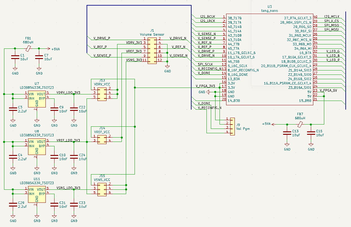
In Lichee Tang Nano GW1N-LV1QN48C6/I5 has max PLL frequency 450MHz. If clocked from I2S MCLK signal 12.288MHz, with integer multiplier max frequency is 442.368MHz
This frequency used as DDR clock gives 884.736MHz sampling rate (resolution). With DDR x8 serdes, FPGA may process 8-bit deserialized data at 110.592MHz.
OSER8 DDR serializer takes 8 bits of data at DDRCLK/4 clock (110.592MHz), and shifts them out at DDRCLK*2 rate (884.736MHz).
ISER8 DDR deserializer shifts in serial data sampled at at DDRCLK*2 rate (884.736MHz) and provides 8 bits of data at DDRCLK/4 clock (110.592MHz).
I've tried to write DCO with OSER8 LVCMOS33D differential output working at these rates.
No timing violations according to place&route timing analysis.
There is a bit faster gw1n - uv (high performance) vs lv (low power). uw-6 has 500MHz max PLL frequency, and 983.04MHz sampling rate with 491.52MHz DDR clock.
But there is no such cheap small board like tang nano on this chip - you have to solder qfn48 with 0.4mm pitch yourself.
Similar Lattice FPGA machxo2 -4 speed grade based TinyFPGA AX2 board has 269MHz max DDR clock (rounded to MCLK - 258MHz), and would have sampling rate 516MHz - almost twice lower.
As well, TinyFPGA AX2 is out of stock everywhere, while tang nano are available, at least on aliexpress.
Ideas - how to increase sampling rate even more:
Utilize i/o delay blocks, use several pins to send or receive the same signal, with different delay.
For output, use two DDR outputs with delay difference corresponding to half of DDR sampling rate. Odd 8 bits of 16-bit parallel value should be routed to one pin, and even 8 bits - to another. Connect together via resistors - and you will have better edge resolution - with 1.65V in DDR half period where two inputs have different values.
For input, put input signal on pair of inputs, use two IDDR inputs with delay block, having DDR sampling rate / 2 phase difference.
Mix two 8-bit values from deserializer to 16 (odd/even).
This approach can be scaled. Doubling of number of inputs / outputs for the same signal may give double resolution.
E.g. quad inputs with different delay give quad resolution (3.5GHz)