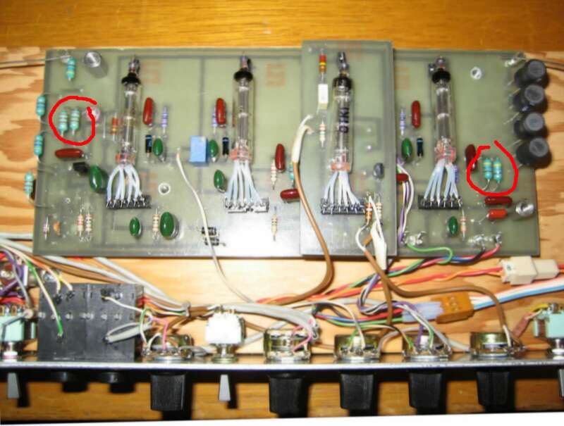
Replacing the oscillators in the Etherwave Theremin?

Posted: 11/17/2019 5:45:08 PM
ILYA

From: Theremin Motherland

Joined: 11/13/2005

The oscillators must run under conditions:
1. Be wide range tunable after assembling of instrument (trimming inductors L5 and L6 in EWS)
2. Be comfortable (fine) tunable at regular operation (electronic tuning in EWS)

These conditions may contradict each other. Fortunately, the variable inductors in my last design combine advantages of both. The topology of oscillator is the same to "Paradox" (excluding +5V vs. +9V power supply).

I see only one easy way to replace trimming inductors in EW -- bank of capacitors with values, say, 2-4-8-16-32-64-128 pF connected in parallel to C1/C5.
But tuning can be confusing for those who are not familiar with binary notation.

And yeah, any oscillator is suitable for digital clock inputs. But the and/or/xor/D-trigger based mixer produces aliasing. So the filtering and ordinary diode mixer is used in Paradox.

Posted: 11/17/2019 6:03:04 PM
ILYA

From: Theremin Motherland

Joined: 11/13/2005


BTW,

the dewster's oscillator with air core coil is working fine in terms of thermal stability. With small amount of ferrite I have a thermal drift of audio frequency about 9 Hz after 5 minutes and less 22 Hz after 25 minutes of warming, in the absence of correlated thermal drift! (the second oscillator is crystal type)

Posted: 11/18/2019 4:10:39 AM
CharmQuark

From: Sweden

Joined: 11/14/2019

I take it that "EWS" is some sort of shorthand for the Etherwave theremin and you are discussing my top post about replacing those oscillators? Otherwise I'm not sure I understand fully what you mean. Currently I'm more interested in your Paradox design than the Etherwave.

But, I suppose I could do a digital control with a mux or relays to connect capacitors or inductors in a 1,2,4,8... fashion, tuned by a single pot or encoder wheel. Added complexity, but the user experience may be improved and no need to understand binary. Problem here is a longer track path for the capacitors or inductors, which isn't ideal. But I think there is encoder wheel with binary pattern (or perhaps gray code) output. Edit: but wait! If the trimming inductor in the EW can be replaced by a bank of capacitors 1-128p, they surely can be replaced by a single trimming capacitor of 1-255p. Even if that range is high, a reasonable amount of fixed and one smaller trimmer (say 1-60p which is common) would suffice, right? Why then have people not exchanged the hard-to-source inductors for the EW with easier-to-source fixed caps and ordinary cap trimmers?

What do you think of the schematic I posted two posts back? The EW, but with the oscillators of the "wine box theremin". I'm currently experimenting with a single oscillator from that design (wine box).

Edit: If I had all time in the world, I would put critical components in a oven with a PID control. And/or try to use crystals for the fixed oscillators. But that is a whole project of its own...

Posted: 11/18/2019 3:54:03 PM
ILYA

From: Theremin Motherland

Joined: 11/13/2005

yes, EWS=Etherwave Standard

"But, I suppose I could do a digital control with a mux or relays..." - CharmQuark

IMO an unjustified overcomplication.

The tuning  is required only once, after assembling (well maybe several times after falling to the floor).


"can be replaced by a bank of capacitors 1-128p" - CharmQuark

that was just a concept.

The EWS inductors have a trimming range about +-25%. If we replace it by fixed inductor plus trimming capacitor, the capacitor range should be also +-25%.

Back to EWS:

The new value of C1 have to be 2475 pF plus trimming capacitor 0...1650 pF in parallel (unrealistic!).

So the bank must include values: 1650/2, 1650/4, 1650/8 pF and so on.

What is the lower limit?

IMO about 12...25 pF, as the fine tuning of EWS ("Pitch" knob) has a capacitance equivalent of 50 pF (very approximately).

As a result,  7 of standard caps: 820, 430, 220, 110, 51, 27, 13 pF.

Posted: 11/18/2019 4:00:56 PM
dewster

From: Northern NJ, USA

Joined: 2/17/2012

"I take it that "EWS" is some sort of shorthand for the Etherwave theremin and you are discussing my top post about replacing those oscillators?"  CharmQuark

EWS = Moog Etherwave (Standard)

"If the trimming inductor in the EW can be replaced by a bank of capacitors 1-128p, they surely can be replaced by a single trimming capacitor of 1-255p. Even if that range is high, a reasonable amount of fixed and one smaller trimmer (say 1-60p which is common) would suffice, right? Why then have people not exchanged the hard-to-source inductors for the EW with easier-to-source fixed caps and ordinary cap trimmers?"

I don't have the super direct experience that ILYA has here, but mathematically, any variable C going directly from the pitch antenna to ground will have much more influence over the audio pitch than you might naively expect.  I don't think you would ever need to adjust the padding by more than several pF for environmental reasons, perhaps a bit more if you are swapping out antennas.

"Edit: If I had all time in the world, I would put critical components in a oven with a PID control. And/or try to use crystals for the fixed oscillators. But that is a whole project of its own... "

IMO highly complex analog Theremins aren't worth the effort, though simpler ones probably are (somewhat depends on your background).  A digital approach can wipe all sorts of touchy and hard to find passives off the board, eliminate tuning headaches, and give you fantastic linearity along with all the voicing options in the world.  But it's a completely different beast from a design standpoint.

Posted: 11/18/2019 4:12:13 PM
dewster

From: Northern NJ, USA

Joined: 2/17/2012

"Already built the variable pitch oscillator from the "Wine Box Theremin" to check sensitivity at higher frequencies. No good result yet. I'm sitting in a noisy environment, in a flat with computers and several other things that has SMPTs, CPUs and what not. Need to plan for some more serious experiments with a little more control over the environment (incidentally, 50 Hz has *not* been a problem. The problem is the sensitivity of the antenna, which is way to low. On reason may be the proximity to metals here." - CharmQuark

This is a common misconception.  Metal several inches away from the oscillator, and maybe a foot or so away from the antenna, probably won't do much.  Neither will computers and other electronics.  I sometimes a see very far field response to my monitor going to sleep / waking up, but that's about it.  The wash machine turning on and off spikes things for a bit, but I assume that's via the common ground.  Make sure you have a good ground, as that can influence things more than anything else.  Mains wiring a foot or two away from the pitch antenna can easily induce hum.

I simulated and benched a bunch of oscillators on my analog Theremin thread, some were intrinsically unstable due to internal noise and such, most weren't.  Make sure you locally regulate the voltage supply going to your oscillators via 3 terminal devices (and RC decouple multiple oscillators being fed from a common regulator), as this is the first line of defense in terms of stability.

Posted: 11/18/2019 4:19:12 PM
ILYA

From: Theremin Motherland

Joined: 11/13/2005

What do you think of the schematic I posted two posts back? The EW, but with the oscillators of the "wine box theremin". - CharmQuark

Suspicious schematic. For linearization effect the ratio of EQ inductance (10+10+10+10=40 mH) to tank inductance (1mH) shold be around 400.

Posted: 11/18/2019 7:51:59 PM
Thierry

From: Colmar, France

Joined: 12/31/2007

The wine box theremin has never proven to be well playable. I refrained from building it after I found out that it was not really developed, but the schematic is a copy-paste assembly from several different public theremin schematics which for themselves weren‘t already great. But the circuit parts as assembled in the wine box schematic were never designed to work together.

Posted: 11/19/2019 2:58:18 AM
CharmQuark

From: Sweden

Joined: 11/14/2019

yes, EWS=Etherwave Standard"But, I suppose I could do a digital control with a mux or relays..." - CharmQuarkIMO an unjustified overcomplication.The tuning  is required only once, after assembling (well maybe several times after falling to the floor)."can be replaced by a bank of capacitors 1-128p" - CharmQuarkthat was just a concept.The EWS inductors have a trimming range about +-25%. If we replace it by fixed inductor plus trimming capacitor, the capacitor range should be also +-25%.Back to EWS:The new value of C1 have to be 2475 pF plus trimming capacitor 0...1650 pF in parallel (unrealistic!).So the bank must include values: 1650/2, 1650/4, 1650/8 pF and so on.What is the lower limit?IMO about 12...25 pF, as the fine tuning of EWS ("Pitch" knob) has a capacitance equivalent of 50 pF (very approximately).As a result,  7 of standard caps: 820, 430, 220, 110, 51, 27, 13 pF.

Well, this over-complication were just to mitigate what you thought could be hard for the user, but if it only is trimming once, and perhaps not even by the user, then I don't really see the problem with log2-switchbank (but incidentally, I found that I have a hundred 0-F encoders with binary output just lying here, in a footprint like a large trimmer pot, so that one was easy if it should be on topic! ).

But the main point is: do you say that the EWS trimmer inductor(s) can be replaced trimming the caps in the tank? (I mean, of course they can, but does it work in practice?). I mean, the same thing goes here as the "replacing oscillators" idea. For some reason no one seems to have done it, and the only reasonable interpretation I can do is that it won't work and/or have side effects making it not worth it. On paper it should work.

As I said before, the schematic I posted were cut-and-paste basically, I have *not* recalculated values for any of the components. I also see the mismatch between the antenna coils (according to EWS) and L5. But I have kind of leaved that project altogether, and currently work just with your own "Paradox" that I think is very promising. My idea is to replace the pitch oscillators to be less trimmer inductor and trimmer cap-heavy so to speak and replacing the obsolete AN5265 with another amp. No other modification other than maybe footprints (I work mainly with 0603 for non-power passives).

I haven't solved the volume tuning yet. I would like to replace the large 3.3µH (L3) and your custom C12 with something easier to source. But for the time being I keep this part and just have to source/build the components.

The most important question I have about the design right now, is how much trimming needs to be done on a regular basis? You have the custom caps connected to the front with knobs. Does that mean they are used in such a way that using small trimmer caps would be an inconvenience. I'm focusing on the volume turning circuit. 

@dewster: When I said I'm having proximity to metals (both grounded and floating) I really meant it. I'm almost in a cage and less than a foot away is a large grounded metal case, less than two feet to my right, the same thing. Below, on the desk I have a ESD mat that can be hard to predict thanks to the very large resistance. Two ungrounded metal locker sits about two foots downward, left and right and just a few inches above my head I have a old fluorescent lamp. And SMPS everywhere, some open without shield (but with a little more distance, they should be less of a problem). Normally its no problem at all, rather something that forces me to thing about EMC when doing sensitive stuff. I'm picking up 50 and 100 Hz, ~1 kHz (no idea), a few spikes at several hundreds of kHz (SMPS of some flavor) and have kind of a high noise floor. If I move to the living room, the antenna (just a vertical cable at this point) actually seems to work much better.

Right now I'm reading your thread "Let's Design and Build a (simple) Analog Theremin!" from end to end and testing your oscillators in spice. They are promising and the frequency ranges seems just what I need!

I'm not against digital but for example the "OpenTheremin" doesn't have decent and honest sound samples, not what I have found anyway and I'm not in a mood to starting a whole project for that, with software and whatnot. I'm looking more for something I can test, cad and build in a short time. And I have already a ton of embedded digital projects going on that I need some "vacation" from.

@Thierry: Yep, I kind of guessed that. There is a dozen theremin designs for each honest sound sample out there. The EWS, the Phoneix and the Paradox all has the advantage that you can listen to them on the net.

Posted: 11/19/2019 7:06:11 PM
ILYA

From: Theremin Motherland

Joined: 11/13/2005

There is another possibility - two adjacent inductors like this:


Related thread - http://www.thereminworld.com/Forums/T/32477/russian-rod-tube-theremin

You must be logged in to post a reply. Please log in or register for a new account.