Replacing the oscillators in the Etherwave Theremin?

Posted: 11/21/2019 1:04:42 PM
CharmQuark

From: Sweden

Joined: 11/14/2019

No problem, dewster! Well, I agree with you in your general assessment of oscillators, but I also know there is ways to mitigate drift in RC oscillators, from simple measures to complicated (I also briefly considered to use a DDS from an XTAL, so you get the idea of how much I want to avoid make my own trim caps! I have an old design of a 24 bit software DDS in an MCU, but it cannot reach the frequency needed. I think I can hear you all facepalming from over here! ).

I'm most interested in hearing from ILYA about what he thinks about tuning via the fixed oscillator instead of via the variable pitch osc, regardless of oscillator topology.

As I said, I'm also working in parallel to figure out some way to make own tuning caps (the link you gave me to pitts8rhs design was of course interesting but way to ambitious for me!) and I intend to layout any PCB so the oscillator part can be easy to replace or patch.

Posted: 11/21/2019 2:53:50 PM
dewster

From: Northern NJ, USA

Joined: 2/17/2012

"(I also briefly considered to use a DDS from an XTAL, so you get the idea of how much I want to avoid make my own trim caps! I have an old design of a 24 bit software DDS in an MCU, but it cannot reach the frequency needed. I think I can hear you all facepalming from over here! )"  - CharmQuark

Quite the contrary, my D-Lev uses DDS (50MHz XTAL base multiplied by 59/15 via FPGA PLL to give 196.666667MHz clock) as the digital PLL oscillator, the output of which directly stimulates the LC tank.  Can't beat DSS for rock steady stability and super wide "pullability"!  (Using DSS to generate square waves in a digital Theremin requires dithering, though dithering is probably necessary anyway to properly capture the input via a clocked input.)

"I also know there is ways to mitigate drift in RC oscillators, from simple measures to complicated"

It's not just drift, but phase noise as well.  Look at the output of a "good" RC oscillator on a scope with lots of delayed trigger (>1ms, to decorrelate phase noise) zoomed up to see ns detail.  A good LC oscillator can give ~10ns or so of phase noise, RC will be much higher.

Posted: 11/21/2019 4:27:31 PM
Buggins

From: Porto, Portugal

Joined: 3/16/2017


 I found a general concept I like and try to build it verbatim, but feel forced to tinkering in order to be able to source parts. In the "Paradox" design the oscillators topology has nothing to do with the sound, they could very well be producing square waves. The mixing is, so to speak, already accounted for, by ILYAs eminent design. The only way the waveform is important there, is in the interaction with the antenna. Waveform generation is disconnected from sound mixin[/font][/size][/color][color=#333333][size=2][font="Helvetica Neue", Helvetica, Arial, sans-serif]g by a digital counting stage (again, save for jitter and side channel noise, e.g. loading of power rails).


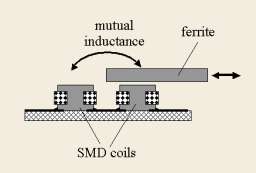
I like Paradox design - "registers" idea, linearization via divider, xtal fixed oscillator, original VCA.
The only thing which is bad here is primitive mixer.
If there is no goal to make design as simple as possible, we could try to replace mixer with more advanced one.
I've played a bit with LTSpice... You can see results below (WARNING: a lot of pictures)

There will be a lot of pots for tuning of each register and mixing them together.

1) Instead of buttons, when mixing registers, use POTs - for proportional mixing of register components.
2) Use better mixer - separate mixer/heterodyne per register - based on analog switch and lowpass filter.

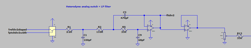
For such mixer, square waveform of reference and variable frequencies is not a problem.
If two squares are passed to enable and input pins of analog switch, output of LP filter will be clean triangle with exact F=F_ref-F_osc. It already sounds better than square.
It's just a starting point for experiments.

Initial LTSpice model to play with on GitHub

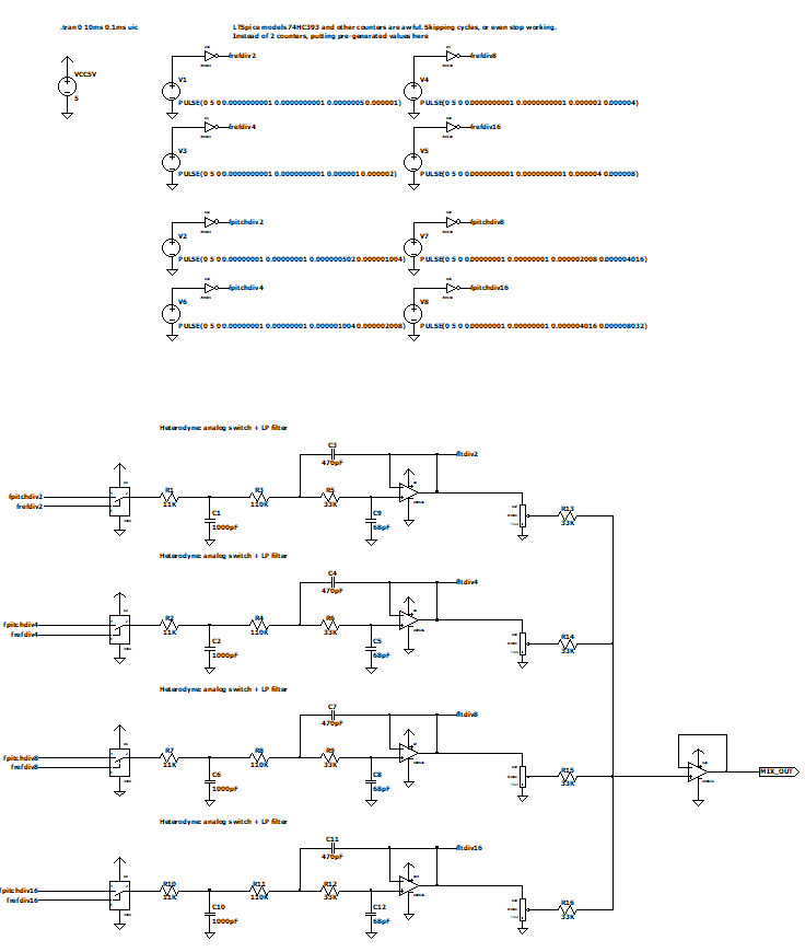
Counter models in LTSpice are don't work for me, so I replaced counter outputs by square pulses of proper frequencies (1MHz for /2, 500KHz for /4 etc).

Output of 4 registers and combined value:


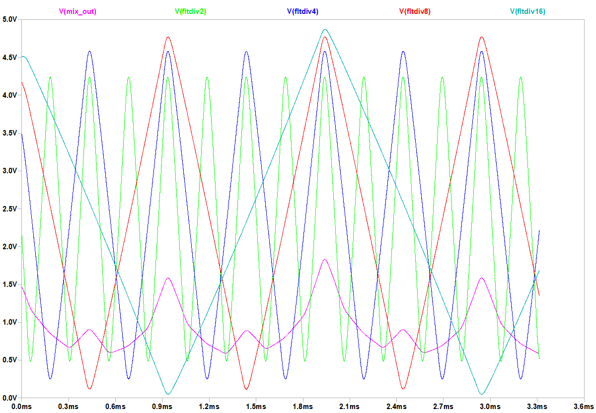
There is almost no difference between reference freq on enable with variable osc on input of analog switch and opposite assignment.
Ref frequency is const, but variable pitch oscillator is nearly const, too, changing for ~3-5% only.

Why this mixer produces triangle for two squares on inputs?
Actually, it's a kind of "moving average" filter for signal on switch input, for time while enable pin of switch is active.
If enable pin duty cycle = 50%, moving average filtered square is triangle.
We can reduce duty cycle, making enable impulses shorter and shorter. For shorter enable pulses, shape of heterodyne output is getting closer and closer to shape on switch input.

If we add pot to change pulse width from very short (~1%) to wide (50%), we can control averaging filter. For square on input, output shape will morph between square and triangle.
As well, it make sense to add pot for changing of enable pulse phase. Phase shift of input signal is applied 1:1 to output signal. It would allow us to mix registers with different phase shift (I believe, relative phases are audible important when mixing several registers).

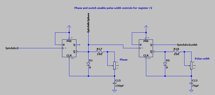
It's similar to 555 timer monostable schematic, just on D triggers instead of 555. (555 did not work for me, I've tried).
First pot shifts positive edge of signal by up to 0.95 of period.
Second pot changes pulse width between 0.01 and 0.5 of period.
RC should be tuned separately for each register.

Then, we can shape input signal as well.
Since it's either fixed frequency or changes only by 3..5%, we can apply a lot of signal shaping techniques which are not available for audio signal frequency ranges. E.g. we can use RLC bandpass filter to get clean sine wave from square.

Let's add pot to morph input signal between sine and almost square (and even some strange waveform, I don't know how to name it).

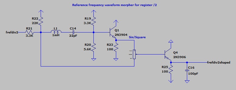
With short pulse width this shape will be converted to register audio signal as is. With increasing of pulse width, upper frequencies are getting filtered out.
E.g. sine becomes really pure after this filter.

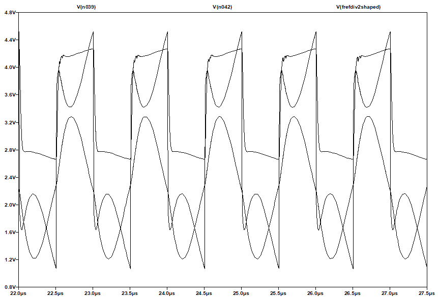
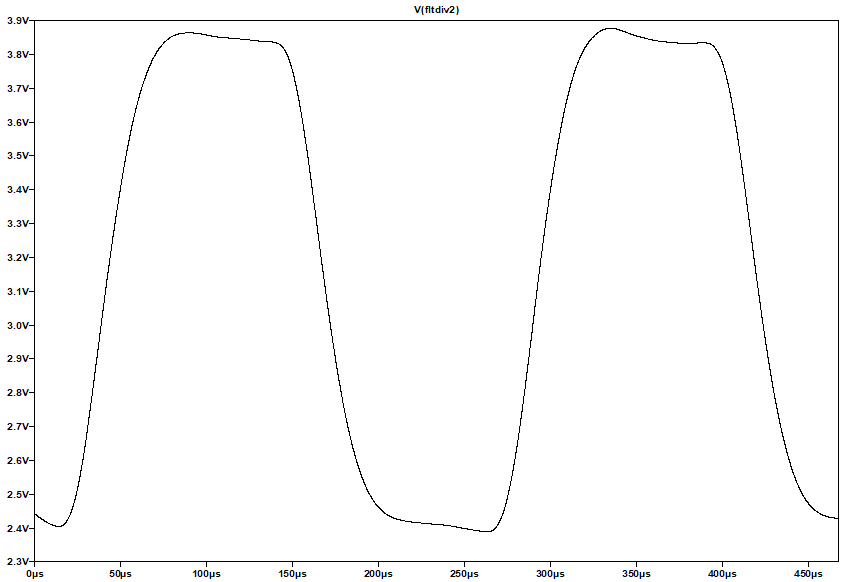
Two signals mixed with pot to create different shapes. In middle position it's close to square wave. Below you can see sine, strange shape, and mix of them.

Mixer inputs. Analog switch "enable" pulse "samples" waveform of switch input signal.

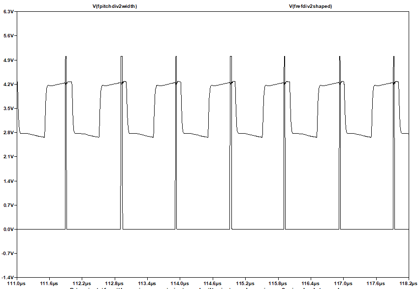
Mixer output for these inputs: shape is almost the same as input waveform, because sampling pulse is short.


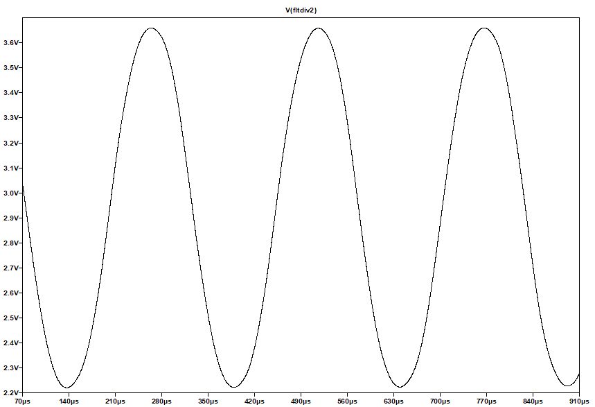
When shape pot is close to 0 position, and pulse width close to widest, output of heterodyne is very clean sine:

It's just a sample shape control. Any other may be used.

LTSpice model with 3 additional pots per register.

Only /2 register has pulse phase/width and signal shape pot controls in this model. 
You can add them for the rest 3 registers.
They should be tuned to lower frequencies: phase/width - increase capacitors *2, *4, *8 times.
For signal shape control, use RLC calculator (probably, you would just need to use *4, *16, *64 multiplier for caps).

In proposed design, there are 4 pots per register:
* phase shift (for relative moving of register signals)
* pulse width (moving average filter control)
* shape (sine .. square .. near sawtooth probably)
* volume of register (for mixing in different proportions - replacement for pushbuttons of original paradox).

In total, there are 16 pots in this mixer

But I believe there is a really wide range of possible shapes is possible to achieve with different pot positions.

Sine / triangle / square / and much more waveforms, mixed from several registers with different phase and amplitude.

UPD: spice models for used components are available on GitHub 

Posted: 11/21/2019 7:47:50 PM
ILYA

From: Theremin Motherland

Joined: 11/13/2005

"what he thinks about tuning via the fixed oscillator instead of via the variable pitch osc" -- CharmQuark

ILYA thinks that 3 trimmer inductors in Paradox is some kind of overkilling.
If you have assembling experience, low tolerance components (including antennae) it’s enough to have only two trimmer coils. Third is fixed iductance.
Be it FPO coil,  VPO coil or volume coil -- it does not matter.
Each option has its pros and cons.

FPO=Fixed pitch oscillator
VPO=Variable pitch oscillator

Posted: 11/22/2019 7:01:18 AM
Buggins

From: Porto, Portugal

Joined: 3/16/2017

More on Paradox design improvements: analog wavetable based synthesis.

Better idea for cool mixer / waveform generator for Paradox-like analog theremin (based on some ideas from my previous post).
Overall complexity of new schematics will be lower, with much better usability.

Let's setup waveform using slide fader pots, like in graphical equalizer.
Instead of mixing 4 "registers" with f, f/2, f/4, f/8 frequencies, just use two buttons to setup octave shift:
00: base octave
01: -1 octave, frequency = base/2
10: -2 octaves, frequency = base/4
11: -3 octaves, frequency = base/8

Connect 16 sliders to 16 to 1 analog multiplexer / demultiplexer inputs. Pass 4bit counter output value to address inputs, and you would get voltage corresponding to position of each slider for each of 1/16 intervals of signal pitch.
We need to pass through all 16 intervals within single heterodyne cycle, so XTAL based reference frequency oscillator is needed, with 8-16 times bigger frequency than one in original design - e.g. 16 or 32MHz xtal can be used. Oscillator output should provide divider output with 4 reference frequencies - e.g. 16,8,4,2 MHz. One of them will be routed to use as fixed frequency in heterodyne (use 4->1 mux controlled by octave selection buttons).
As in original Paradox, pitch variable oscillator will produce f/2,f/4,f/8,f/16 selected using 4->1 mux by octave number.
XTAL mux gives ~16 or ~8 times bigger frequency, which should be passed to 4bit counter to provide "wavetable address".
Wavetable address should pass all 16 samples once per variable oscillator divider output cycle. As output of wavetable, we should see waveform set by slider positions.

Again, let's use analog switch + LP filter as heterodyne.


On analog switch input, we shall pass buffered waveform mux output.

On switch enable input, we need to pass pulse with pitch variable mux out frequency, with selected duty cycle.
Width of enable pulse determines moving average filter window length.
The shorter duty cycle is, the closer is output of heterodyne to original waveform from switch input.
Max duty cycle is 50% - max averaging. For square waveform set for input, triangle will be generated. For sin-like waveform, output will be almost clean sine.
For duty cycle 50%/16=1/32, output will be source waveform linearly interpolated (no ladder effect).
For shorter pulses, "ladder" effect of source waveform will be more and more visible (more higher harmonics in audio).

To control pulse width, we can use half of phase/pulse width part from previous post - single D-trigger with async reset.

Pot will be used for setting of pulse width from very short to ~50% of pitch osc mux frequency.
The problem here is that circuit timing should be adjusted for each octave to keep available pulse duty cycle in range 0.001..0.5 for all pot positions and all octaves.
Proposed solution: use 4->1 mux with octave number as address, with capacitors bank on inputs: caps C, C*2, C*4, C*8 on inputs 0,1,2,3.

So, we will have 16 fade slider pots to specify waveform, 2 pushbuttons to select octave, 1 pot to control fitering, and as result we will have waveform set by faders on heterodyne output. Waveform will remain mostly the same for all output frequencies, not counting audio range LP filter.
E.g. for small averaging filter setting, and low audio frequency, higher harmonics of waveform ladder effect will be audible (wider spectrum for low notes).

It would be nice to add bass/treble filter pots for additional tuning of sound spectrum.
Tunable voice formats filter on output might allow to add interesting effects.

As well we can go further.
Let's double hardware to get even better sounding.

Add one more wavetable (16 more pots, 16->1 mux, optional pulse control or one from first wavetable may be used, mixer).
This will give us additional waveform sync to first one, but with different shape.
Add low frequency oscillator with sine or triangle shape, adjustable middle point, amplitude and frequency.
This oscillator will be used to fade between two shapes, to make even better sound
If separate register (octave) cirquits added to second wavetable gen, it would be possible add mixing two different octaves,
like octaver effect, or get other interesting sound effects as mix of two waveforms.


UPD: 
Looks like 74HC4067 is fastest available analog multiplexer, with propagation delay address->output ~60ns, and it should be used at address changing frequencies 8MHz or less. On 4MHz there should be sharp enough edges. On higher frequencies I would expect smoothing / averaging of sequential waveform settings. This bound is ok for register 00. For other registers, edges are guaranteed to be sharper.
Using 16MHz XTAL oscillator module, ~2MHz variable pitch oscillator, find dividers / mux mapping and frequencies for all 4 registers:


Code:
XTAL frequency: 16MHz, mux one of 4 divider outputs (/2, /4, /8, /16)
Pitch variable oscillator frequency: 2Hz, mux one of 4 divider outputs (/2, /4, /8, /16)

mux    octave    ref freq div mux    pitch osc div mux
00      0        16MHz/2  = 8MHz      2MHz/2  = 1.0MHz
01      -1       16MHz/4  = 4MHz      2MHz/4  = 0.5MHz
10      -2       16MHz/8  = 2MHz      2MHz/8  = 0.25MHz
11      -3       16MHz/16 = 1MHz      2MHz/16 = 0.125MHz

Looks like 74HC4067 has good enough performance for 16 samples wavetable synth.

Posted: 11/23/2019 11:04:41 AM
CharmQuark

From: Sweden

Joined: 11/14/2019

@ILYA: Aha, ok. Thank you, I was wondering why you do have trimming parts in both oscillators. But I take it that 470µH is just fine in (for example) the VPO and then a trimmer inductor in the FPO? The pitch tuning pot C6 seems little more critical for the antenna adjustment, or can it be moved to the FPO as well?

Finding an amp to replace AN5265 turned out to be much harder than I thought. Every time I find a promising amplifier with DC volume control, it is obsolete and/or is not in stock at mouser or ELFA. I have found a few Class D amplifiers, but since I have virtually no experience of audio stuff (has never been my thing really, all analog stuff I usually do is about measurements and instrumentation) I'm worried that class D cannot be used here? (If they have integrated modulator/PWM generation it can work, right?). Edit: Of course, after searching for a day, browsing datasheets and writing the post, within 20 seconds, I found a part dealer near me who has the TDA7052AT.

Edit2: ILYA, any caveats with component values? In general, I'm going to use 1% 0603 SMD part for passives that don't dissipate lot of powers, C0G or NP0 capacitors where possible BC847/857Bs or Cs. I haven't found the inductors (T79x Mitsumi or M1710A) yet or their datasheets, but working on it.

@Buggins: Great posts! I was just thinking of having pots instead of switches for the mixing, but for now I think I use the current design in this part unaltered, to save time (one reason is that I found a box of HEX encoder switches and I would be a fool not to use one of those in a prototype). Even if I wanted to do just one PCB, I'm going to create about 5 boards for prototyping. One for FPO, one for VPO, one for the counter and mixer, one for the volume control and last one the amplifier. And maybe one for the PSU (I'm planning to use local LDO regulation on each board and supply the +12V from a linear lab supply during testing. When everything is working, I will spin another board with everything on it.

If time allows, I going to revisit the mixer design. I'm currently routing the mixer board.

Posted: 11/24/2019 8:08:55 AM
ILYA

From: Theremin Motherland

Joined: 11/13/2005

"or can it be moved to the FPO as well?" - CharmQuark

Bad idea.
The FPO services both parts -- pitch and volume sides. If "Pitch" tuning will be moved to FPO, it will  influence to "Volume" tuning.
What is tolerated for coarse ("factory") adjusting that is not tolerated for fine ("everyday") tuning.

"I have found a few Class D amplifiers,"  - CharmQuark

Does it have the true "continuous" DC volume control? All the D amps I had find are implement an algorithm like this: (Control Voltage) -> (ADC) -> (resistor matrix around input opamp).

Posted: 11/24/2019 12:18:15 PM
ILYA

From: Theremin Motherland

Joined: 11/13/2005

Just an another way to trim inductance.

Doug Forbes (in topic) bends the leads of two inductors to variate a clearance and change this way the mutual inductance.
With SMD inductors the mutual inductance can be changed in such the manner:

No ideas about resulting range (needs to try), but SMD coils definitely must have an "open field" design.

Posted: 11/30/2019 9:32:57 PM
CharmQuark

From: Sweden

Joined: 11/14/2019

Again, thank you all for you insights! I have nothing really new to report, had a busy week. But now I'm routing the boards and a first shipment of components I didn't already have has arrived. In my first prototype I will use trimmed components, but nothing self-built but COTS trimmer not intended for a front panel. I will have to solve the "user interface" trimming later. First up is a multi board prototype. Since I'm etching my own boards for the prototype I have no lead times for the PCBs at least! But the price is perhaps a sub-optimal routing since I'm gonna use single sided boards (and, like in the original I have 'upgraded' to 1206 components to ease the single side routing). If everything works and I'm satisfied with the design, I'm gonna route a more proper two sided PCB for external manufacture (and probably switch to 0603 which is my preferred go-to size for passive SMDs).

I've used footprint for old IF trimmer inductors/transformers, I hope they will work. In series with CD43 or CD54 inductors. They may have piss-poor EQ and is more intended for SMPSs and such, but that's the only feasible option I have right now.

You must be logged in to post a reply. Please log in or register for a new account.