I'm starting this thread to discuss (probably) new kind of oscillator.
Separate thread will help not to miss interesting idea lost in tons of other posts.
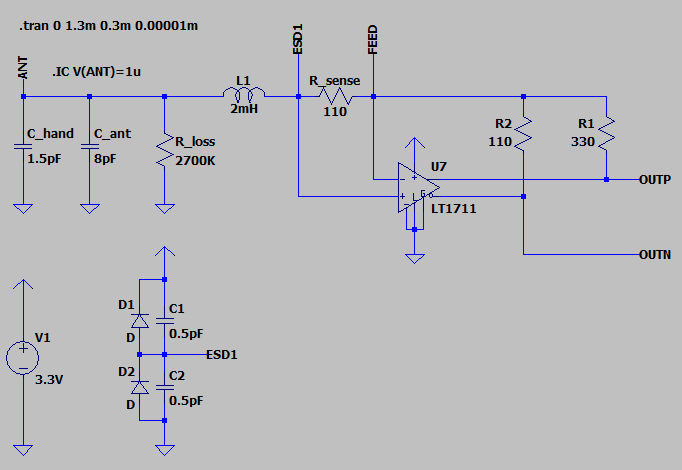
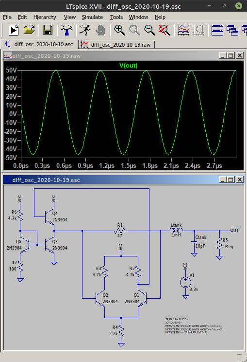
Simplified schematics: LC tank + resistor + differential amplifier (comparator)
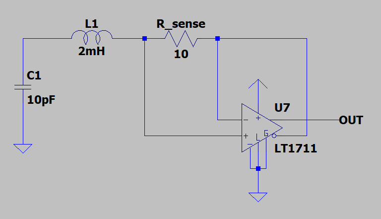
Is current sensing differential amplifier LC oscillator known?
Last invention of LC oscillator mentioned on Wiki is dated 70 years ago.
Armstrong, 1912
Hartley, 1915
Colpitts, 1918
Vackar, 1945
Clapp, 1948
I couldn't google anything similar to oscillator proposed by Eric (dewster on TW).
The only current sensing solutions I found are related to power consumption measurements.
If it's new kind of oscillator, it looks like a real invention.
Wallin, 2020
First description of Eric's idea can be found in this post of "Teensy 4.0 600MHz ARM Cortex M-7 MCU - ideal for digital MCU based theremin?" thread.
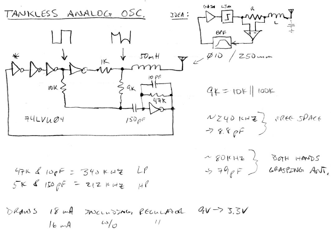
If you are going to have a high speed op-amp in there, you might try differentially sensing the coil drive current, which is 180 degrees out of phase with the drive voltage (the following was just hacked together a while ago with CMOS and could be improved, not sure the BPF is good or necessary, and of course the sensing R can be a Q killer)If you are going to have a high speed op-amp in there, you might try differentially sensing the coil drive current, which is 180 degrees out of phase with the drive voltage (the following was just hacked together a while ago with CMOS and could be improved, not sure the BPF is good or necessary, and of course the sensing R can be a Q killer)
-- dewster
Correction:
I actually came up with that circuit in this post on 12/10/2013.
-- dewster
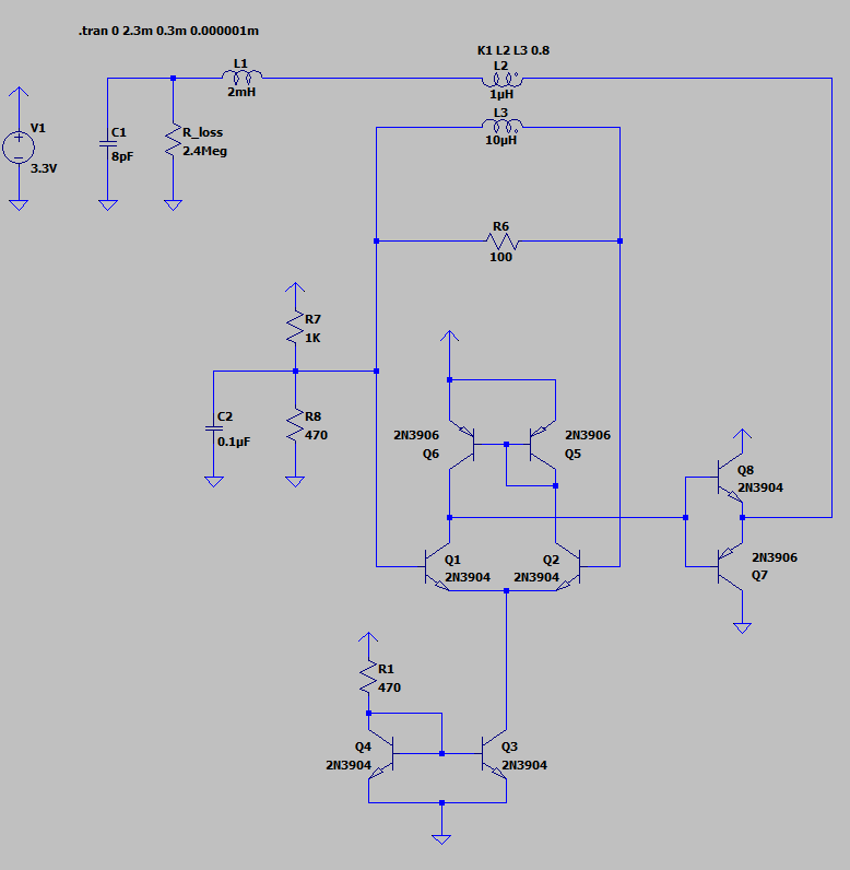
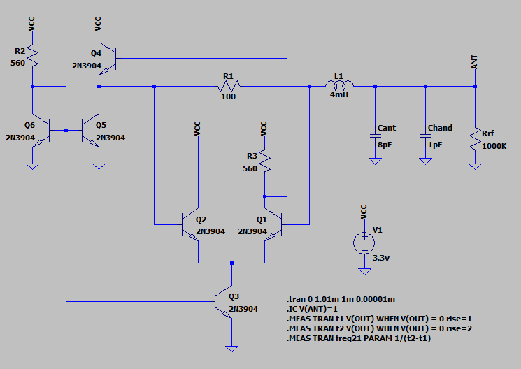
Post with BJT implementation test report in "Let's Design and Build a (simple) Analog Theremin!" thread.
I believe it's awesome idea.
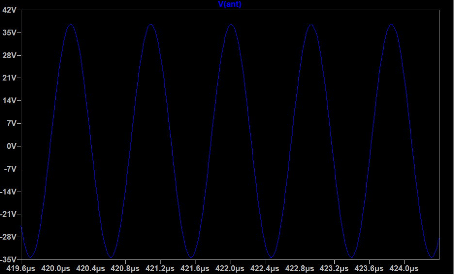
Stable 400Vpp swing on antenna oscillator is probably the best one for theremins.
I wonder if it could be possible to see in future wiki article https://en.wikipedia.org/wiki/Wallin_oscillator ?