Armstrong, Hartley, Colpitts, Clapp, Wallin...

Posted: 12/10/2020 5:29:37 PM
Buggins

From: Porto, Portugal

Joined: 3/16/2017

Soldered LT1711 current sensing oscillators, and got first test results.

In general, oscillator is working.
Bad news - when antenna is touched, it switches to high frequency self-oscillation (5-10MHz).
Looking for the way to fix it.


So far, trying to design symmetrical BJT current sensing oscillator.
It's cheaper than fast differential amplifier ICs and comparators.

Symmetry is beautiful, so such device should have better performance

Took two differential cascades - NPN for sensing near Vcc, and PNP for sensing near GND.
Then both signals are mixed to form output.
Is there some better solution to give 0..3.3V output?


Sensing gives smooth symmetrical drive signal, but with reduced swing: 0.7..2.6V

Antenna swing is 120-140Vpp.


Model file: link to GitHub

Posted: 12/11/2020 6:13:30 PM
dewster

From: Northern NJ, USA

Joined: 2/17/2012

Doin' Due Diligence: Differential Oscillator (6 Transistor)

This oscillator has been running on my bench for a few days now, so I thought I'd play with it a bit more and document the features.  Here's the circuit:

And here it is running on the bench (go little oscillator!):

Here's the LTspice file: https://www.mediafire.com/file/fllsgwfsho4ewsw/diff_osc_6xistor_2020-12-11.asc/file

- Coil is 4mH on 60mm diameter PVC pipe, 50 ohms DCR.
- Draws 5.4mA @ 3.3V.
- Very stable with varying supply voltage.
- Very stable with any antenna (that I have on hand & tried).
- Hard to stall (have to touch antenna bare metal, insulated is OK).
- Pops right back to oscillating normally after stalling.
- Nice digital drive waveform.

It has a very high antenna swing voltage (measured via 1pF series | (83pF + 15pF scope probe)):
- 10mm dia / 300mm long rod: 270Vpp @ 747kHz
- 10mm dia / 360mm long rod: 264Vpp @ 727kHz
- 10mm dia / 500mm long rod: 244Vpp @ 681kHz
- 22mm dia / 450mm long rod: 254Vpp @ 661kHz
- 105mm x 235mm plate: 250Vpp @ 683kHz

This is a really nice oscillator!  Had I run across it earlier on it might have ended up in the D-Lev.

[EDIT] Just tried a 0.5mH coil:

- 10mm dia / 360mm long rod: 98Vpp @ 2.14MHz

I see some amplitude and frequency instability with this coil, so this oscillator is better for lower frequency use (normal Theremin frequencies).

[EDIT2] Very sorry, but apparently there has been a systematic error in my antenna voltage swing measurements, see this post for details.   The numbers above should be more like 200Vpp.

Posted: 12/11/2020 6:37:38 PM
ILYA

From: Theremin Motherland

Joined: 11/13/2005

My five cents:
-- can generate on coil SRF (adjusting of R1 may be required).

Posted: 12/11/2020 6:53:42 PM
dewster

From: Northern NJ, USA

Joined: 2/17/2012

"can generate on coil SRF (adjusting of R1 may be required)."  - ILYA

Ah, a very good suggestion for experimentation!  I put the 4mH coil back in circuit and removed the antenna, with the unconnected scope probe placed nearby.  There is a nice stable sine wave @ 1.33MHz which must be very near the SRF for this coil.  Working backwards, this gives:

  C = 1 / (L * (2 * pi * f)^2) = 1 / (0.004 * (2 * 3.1416 * 1,330,000)^2) = 3.6pF

Not too shabby!  The dangling end wire is contributing some, but the bulk is likely intrinsic C of the high Z end of the coil.  A good reason I suppose to limit overall coil area (not something single layer solenoids are good at - calling Roger and his fancy coil winder!).  Also seems to be an argument for the use of thinner coil winding wire.  Hmm...

Posted: 12/12/2020 7:14:37 PM
Buggins

From: Porto, Portugal

Joined: 3/16/2017


Dewster,


Your recent model looks really good.

There is no reason to implement symmetric oscillator if it gives the same drive voltage swing.


Are you reusing half of current mirror just for economy of 1 transistor and 1 resistor?

Using R2 value a bit smaller than R5 gives better looking waveforms.

Doesn't it make sense to increase transistors current? As I see from datasheet, hfe has maximum at 5-10mA.

R3,R4 can be removed at least if separate current mirror is used for output stage (2 resistors removed, 1 resistor + 1 transistor added).

Increasing R_sense allows working with lower R_loss, e.g. with R_loss=220K oscillator gives 18Vpp on antenna with R_sense = 100

Still hoping to get oscillation working on antenna touch.


Could you please check on breadboard if adding of 150pF cap between inductor and antenna prevents oscillation from stopping on antenna touch?


Updated model:

Posted: 12/12/2020 9:39:32 PM
dewster

From: Northern NJ, USA

Joined: 2/17/2012

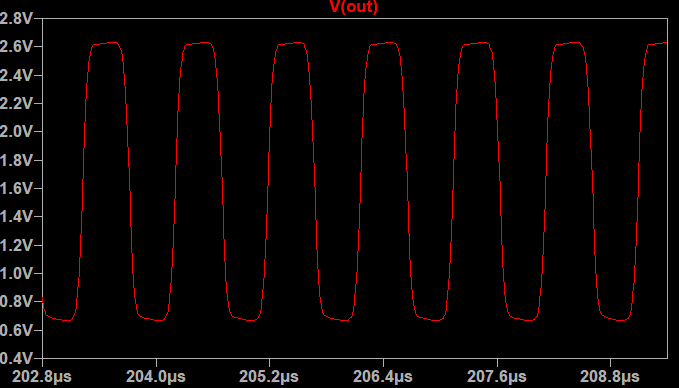
"There is no reason to implement symmetric oscillator if it gives the same drive voltage swing." - Buggins

Your symmetric oscillator is quite pretty, though i haven't bench tested it at all.  I messed with it in simulation this morning some more but couldn't get the drive current to behave and so gave up.

"Are you reusing half of current mirror just for economy of 1 transistor and 1 resistor?
Doesn't it make sense to increase transistors current? As I see from datasheet, hfe has maximum at 5-10mA.
R3,R4 can be removed at least if separate current mirror is used for output stage (2 resistors removed, 1 resistor + 1 transistor added)."

I'm probably missing something important, but I really like to minimize overall current draw.  I'm OK with 5mA, but too much more than that and you might start running into heating drift issues.  The coil itself doesn't need much at all in the way of current.

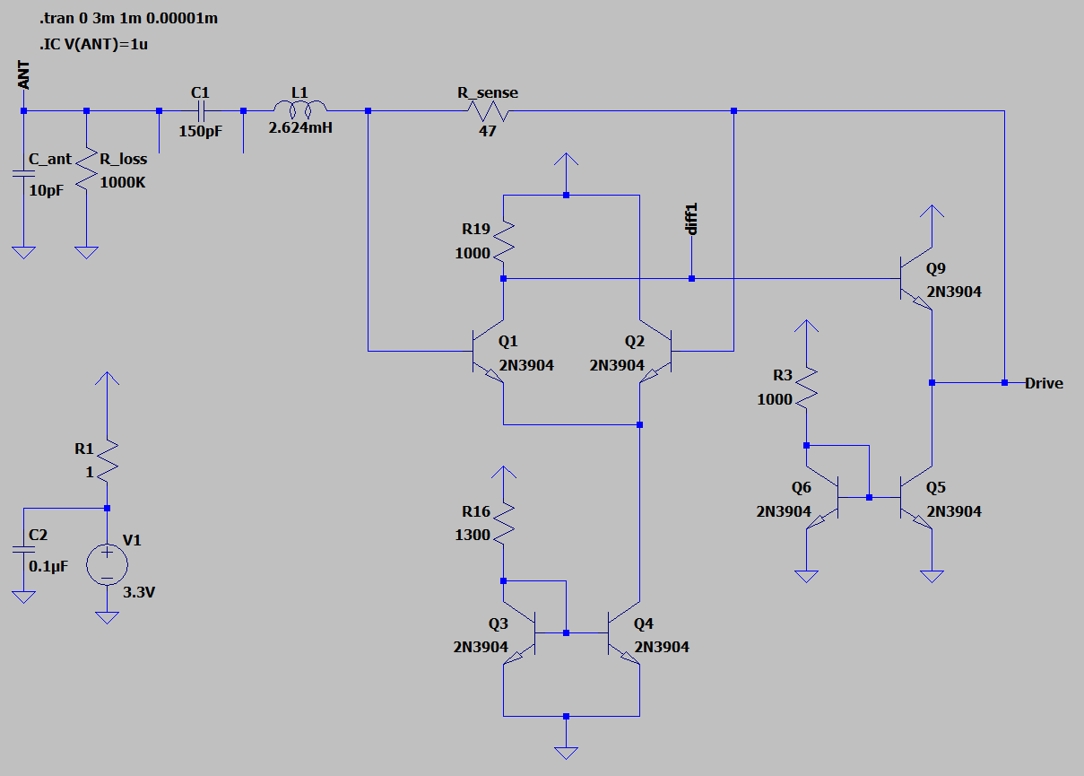
"Still hoping to get oscillation working on antenna touch.  Could you please check on breadboard if adding of 150pF cap between inductor and antenna prevents oscillation from stopping on antenna touch?"

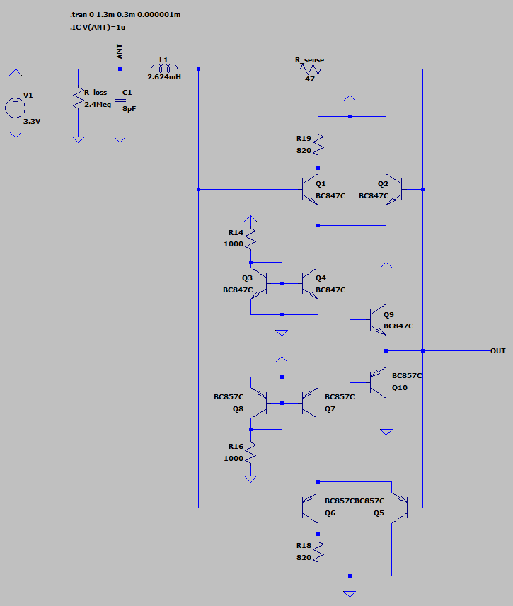
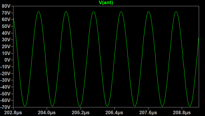
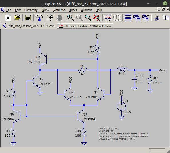
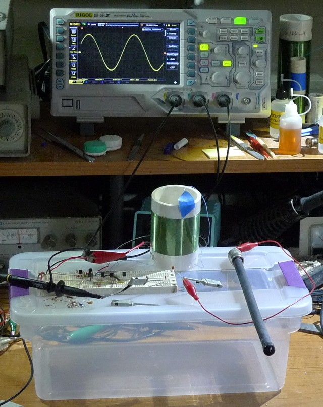
Just tried 100pF in series with the antenna, and touching it kills oscillation.  It must be the resistance of my hand, because I stuck a 103 (10000pF) from antenna to ground and it oscillates at 27.5kHz with 8Vpp, which is the correct calculated frequency for a 4mH inductor.

But I can grab the insulated (heat shrink tubing) rod antenna with both hands and oscillation continues just fine, even without series C.

Even my D-Lev oscillator craps out with actual touching of the bare metal plate, I think that's just life when it comes to simple high Q oscillators.  And insulation is your first line of defense against ESD.  The universe wants you to insulate those antennas! ;-)

[EDIT] This is one of those rare oscillators that actually works better on the bench than in simulation, usually it's the other way around.  Lots of nuance that takes both simulation and bench testing to really grasp.

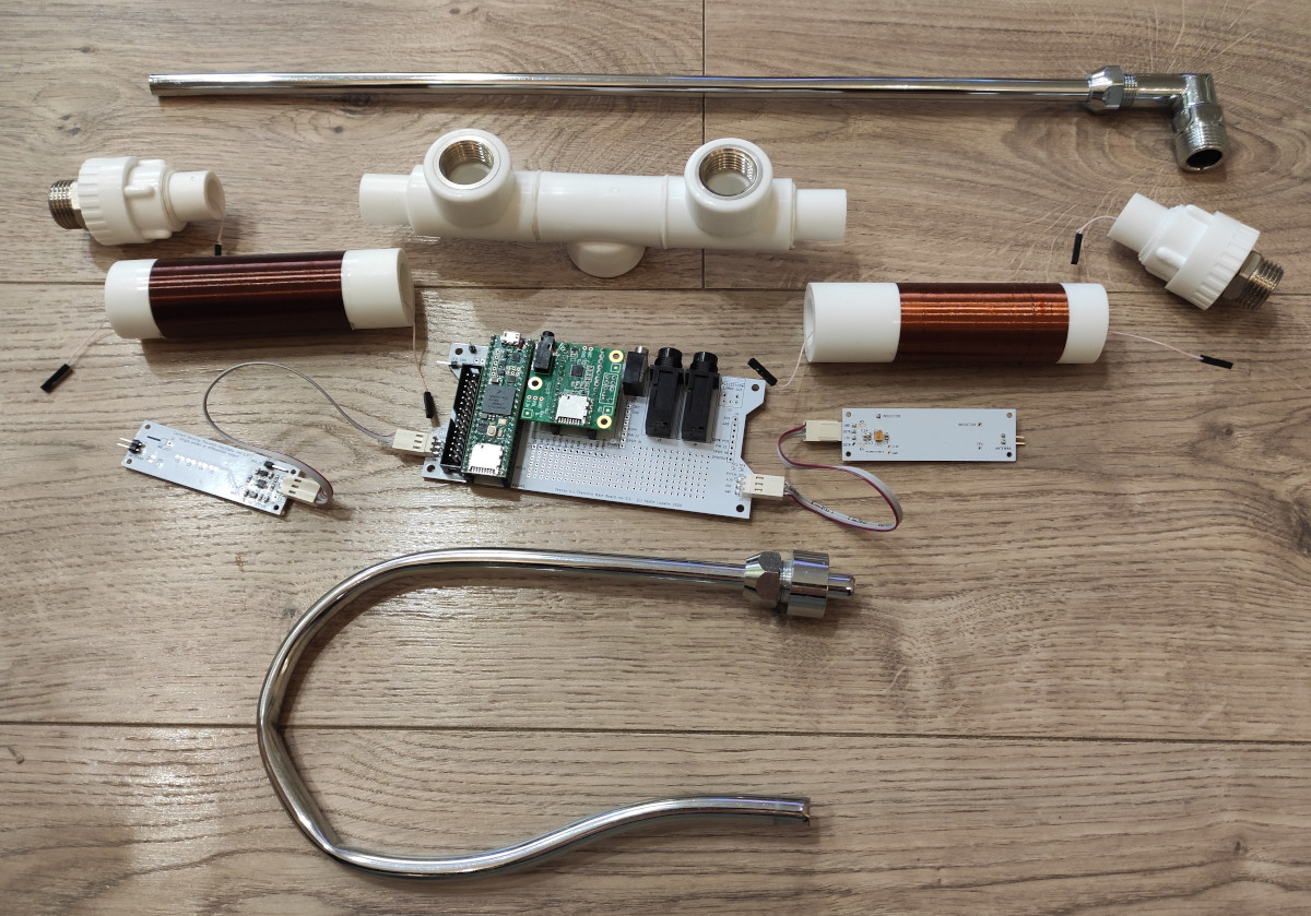
One could make a really neat digital Theremin with this oscillator as it doesn't need the C divider connection that the D-Lev requires, so the coil and antenna could exist together on the other side of a UHF connector, looking all spiffy and coilish and stuff.  Might need larger L values though, like 2mH & 4mH, or 4mH & 8mH, or perhaps a bit of C padding.  The UHF outer connector could be grounded without hurting anything as the connection is low-Z.  No tuning of the C divider would be necessary either.  ESD protection could be on either or both sides of the connector, with no real parasitic capacitance issues.  Lots of possibilities.

Posted: 12/13/2020 6:51:06 AM
Buggins

From: Porto, Portugal

Joined: 3/16/2017

It looks like hand is even worse than shorting R=0 to ground. Otherwise with 100pF decoupling cap it should oscillate as with C_ant = 100pF

How does EW pitch oscillator keep working when touching? Even pitch frequency when touching is the same as if just holding hand near antenna.


Putting oscillator drive on main board and connecting inductor and antenna via coaxial cable is nice idea. R_sense could be the same as coaxial line impedance (50 or 75 Ohm).
Would not connecting of coaxial cable shield from one side only cause any issues?

Posted: 12/13/2020 2:03:00 PM
dewster

From: Northern NJ, USA

Joined: 2/17/2012

"How does EW pitch oscillator keep working when touching? Even pitch frequency when touching is the same as if just holding hand near antenna."  - Buggins

Good question!  I think maybe the EQ coil resonance is sufficiently detuned at touch to unload the tank LC?  A double LC oscillator has that possible advantage here, but so many other downsides.

"Putting oscillator drive on main board and connecting inductor and antenna via coaxial cable is nice idea. R_sense could be the same as coaxial line impedance (50 or 75 Ohm).  Would not connecting of coaxial cable shield from one side only cause any issues?"

I wasn't really thinking of using a coaxial line feed - strict impedance matching probably isn't necessary if the distance isn't too long. 

I wasn't thinking either of putting the guts on the main board (AFE's on the brain) but that is certainly a real possibility.  I wonder how far one could safely stretch this connection?


Posted: 12/14/2020 6:26:53 PM
dewster

From: Northern NJ, USA

Joined: 2/17/2012

Emitter Coupled Logic

Hmm, where have we seen this before?

Posted: 12/15/2020 3:53:22 PM
dewster

From: Northern NJ, USA

Joined: 2/17/2012

Scope Screen Grab

I took a screen grab of the differential oscillator (name suggestion: ECL-LC oscillator) running on the bench with a 4mH air core (50 ohm DCR) and standard length and diameter EW type rod antenna:

This is with a 1:1000 (1pF | 1000pF) C divider located a couple feet from the antenna.  Top trace is stimulus, bottom trace is the divider.  So there is ~200Vpp antenna swing.  You can see the small phase offset between the drive and the antenna (ideally should be a 90 degree lag  - "ELI the ICE man").  ECL for the win!

Most/all of my previous antenna Vpp measurements (and therefore calculations) seem to have suffered from stray C (C divider impedance too high / divider located too close to the antenna).  So the real effective Q of my air core coils (+ antenna @ resonance) is probably more like 100.

You must be logged in to post a reply. Please log in or register for a new account.