


Awesome results.
What is difference from your previous schematics?
ECL shown above is exactly the same as your differential amplifier current sensing, w/o current mirror after output cascade emitter.
Could you please post LTSpice model?
"What is difference from your previous schematics?" - Buggins
No difference from my previous post [LINK] which also has a link to the LTspice sim. I updated the post to note the probable lower Q of my coil, will do the same on the D-Lev thread with more detail.
For the ECL-LC, I can't figure out why the bench oscillator is performing considerably better than the sim (in terms of antenna voltage swing) - usually it's the opposite.
"Probably, your R_loss value 1Meg in model does not match reality." - Buggins
It has in the past. I've even sometimes knocked that down to 470k to get the swings to match.
"As well, on breadboard there are a lot of parasitic caps. Can it increase swing?"
Ah, good call, I'll build one on pad-per-hole vector board. I'd like one of these in it's own little box anyway.
ECL LC Oscillator
Been playing with it on and off for a couple of days now. Here's the updated circuit and LTspice file [LINK]:
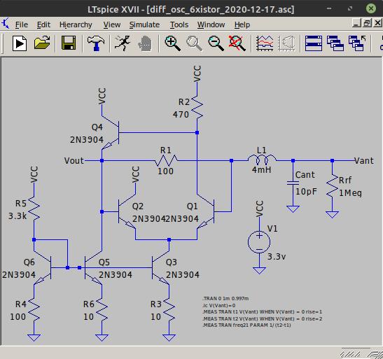
Mainly just impedance changes. First I moved it over to my oscillator breadboard box and rearranged the component layout a little:
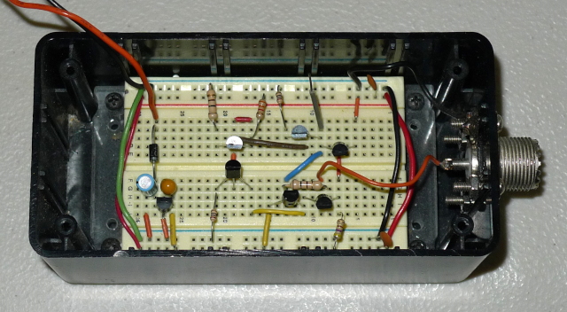
But this wasn't a real test of removing stray C. I was resistant to soldering all those poor little transistors to a vector board that later I might need to heavily modify, or worse maybe not even end up using. Then I hit on the idea of using strip socket to make an easily modifiable semi-permanent board:
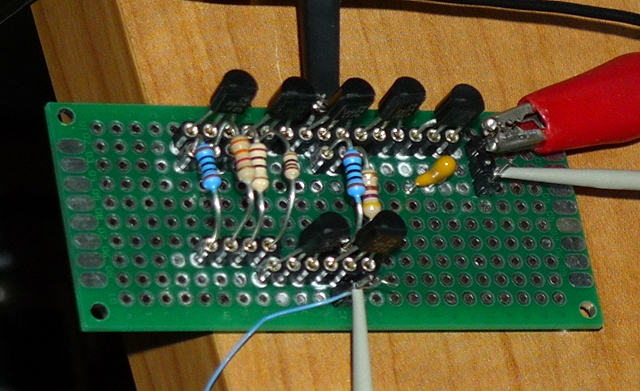
Works like champ! All the transistors in two rows, with passives in-between (regulator is at the upper right in the top row). So if I get tired of it I just yank everything out and stick everything back in my component assortment boxes (waste not, want not). Easily adjust any/all values until I'm blue in the face.
This new tweak on the ECL LC oscillator is ultra stable with varying VCC, the most stable oscillator I've ever encountered in that department. I can twiddle VCC all over the place and it barely budges the frequency, just amazing. It works down to ~2V and has no starting issues whatsoever (some combinations of values have starting issues, this is one thing that is now optimized). Draws ~8mA, >100Vpp on the antenna, very clean and somewhat rounded signal back to the logic that could be used directly. Tried several air core coils, 10mH all the way down to 210uH, they oscillate even without an antenna attached (@ SRF). For the 210uH SRF is ~7.4MHz, and there is some obvious (though not devastating) slew limiting of the constant current drive pull-down at that frequency. I see ~10ns of phase noise (with antenna attached).
Vadim, I think this is the droid oscillator you've been looking for!
[EDIT] Just tried it with an EW type choke & antenna, it's oscillating at 200kHz, ~120Vpp, super clean & symmetric rounded 1.6Vpp drive wave. I've found these RF chokes to be rather stubborn, this one won't do the SRF thing and requires an antenna be attached in order to oscillate. The voltage boost seems to be fine which means the Q is fine, so it's most likely low SRF killing the oscillation. Sticking two RF chokes in series actually makes things worse, a surprise.
Soldering differential current sensing oscillator on prototyping board, similar to dewster's variant, but w/o resistors in current mirror emitters, with separate current mirror for drive cascade, additional buffer on single BJT, powered from 4.5V, with 0.1..3.1V output swing.
I'm using BC549C - measured Hfe is 630-675 (selected matching pairs from 20 transistors - for differential cascade and both current mirrors).
Does it make sense to use higher Hfe transistors? I tried to measure Hfe for 2N3904 - saw values like 100-120...
"I'm using BC549C - measured Hfe is 630-675 (selected matching pairs from 20 transistors - for differential cascade and both current mirrors).
Does it make sense to use higher Hfe transistors? I tried to measure Hfe for 2N3904 - saw values like 100-120..." - Buggins
Probably won't hurt? I don't see any antenna voltage difference with BC549C vs. 2N3904 in my sim. I just put the finishing touches on a ~HV ~HF probe and will properly measure the antenna voltage with it tomorrow.
Here it is running on the bench getting UFO probed: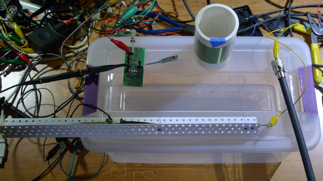
Here's the scope view: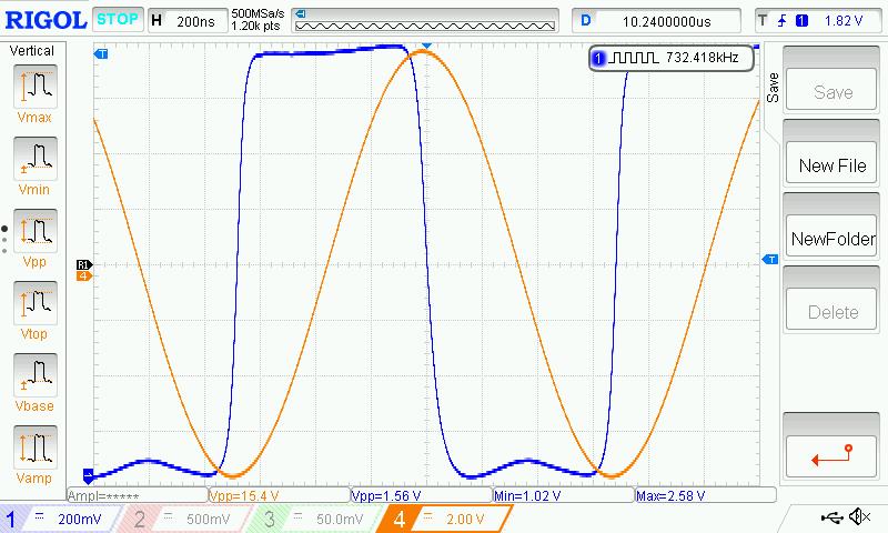
Drive is 1.56Vpp with 1V offset, which gives 1.8V @ center, though you would probably want to AC couple this back to the processor. Alien probe shows 154Vpp at the antenna, which is probably a tad on the low side due to the squarish drive, a coil Q of ~100, and the excellent phase alignment.
And here it is driving an EW RF choke: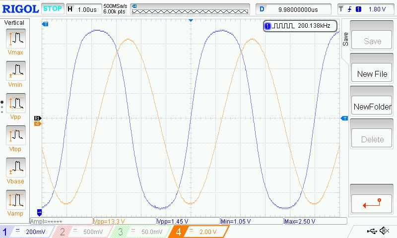
Drive is noticeably more rounded, probe sez 133Vpp at the antenna, phase is excellent. I think it's high self capacitance (low SRF) and not low Q which makes these chokes somewhat problematic to get oscillating in a series type arrangement (where the only C is the antenna). The choke Q here is clearly on the same order as an air-core, which is a bit of a surprise.
Could be my rat's nest setup, but the oscillator today seems to be picking up a certain amount of interference from my two desk lamps.
Thank you a lot for posting your test results!
It looks like your typical R_loss=1Meg simulates too high losses. For better matching of bench results, it should be increased to several megs or even removed. Serial resistance set for inductor models losses well.
Actually, waveform can be controlled by choosing of R_sense.
From one hand, the bigger R_sense is, the more energy is lost on it. But bigger R_sense gives bigger input voltage for differential amplifier. Input voltage affects amplifier output bigger than energy loss on R_sense.
Squarish drive means amplifier gain >> 1.
Decreasing of R_sense decreases gain. When gain approaches 1, drive becomes more and more sine-like and symmetrical, but drive swing decreases a bit.
After crossing of gain 1, oscillation stops.
In your bench, I believe, you can turn drive signal to squarish (and increase antenna swing) by simple increasing of R_sense.
But I feel that more sine-like smooth drive should give better sensitivity of theremin sensor.
Could you please check if it's ok to move inductor+antenna 15-30cm from oscillator board, connecting by wire or by coaxial cable. Allowing to put oscillator on main PCB could simplify design.
How does your bench reacts on antenna touch?
Where did you get EW RF choke? Unsoldered from EW?
Played bit with symmetrical (npn+pnp) differential amplifier simulation.
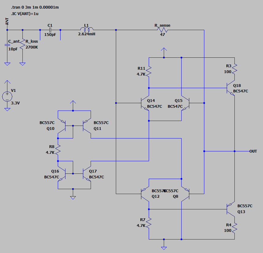
LTSpice model link
Drive signal swing is 0.7V..VCC-0.7V (0.7..2.6V for 3.3V VCC = 1.9V swing).
It has +4 transistors comparing to recent Dewster's schematic and the same number of resistors.
Advantage: it's symmetrical and has bigger output swing. Good for direct connection to digital inputs.
Not sure if this schematic can produce bigger antenna swing than Dewster's one.
"It looks like your typical R_loss=1Meg simulates too high losses. For better matching of bench results, it should be increased to several megs or even removed. Serial resistance set for inductor models losses well." - Buggins
A very good observation, I agree.
"But I feel that more sine-like smooth drive should give better sensitivity of theremin sensor."
I think a certain amount of extra gain is a good thing because gain is lost when the hand is near the antenna. I've currently got a higher aspect ratio 6.186mH air core on there that's resonating at 603kHz, 190Vpp, and I can't stall it even if I grab the insulated antenna with both hands. Whereas with the RF choke I can stall it by pinching the insulated antenna with thumb and forefinger.
Also, a more square waveform has a better defined (in time) digital threshold. You want fast edges (rise and fall times) so noise doesn't influence timing calculations too much, with slightly rounded corners to reduce ringing.
"Could you please check if it's ok to move inductor+antenna 15-30cm from oscillator board, connecting by wire or by coaxial cable. Allowing to put oscillator on main PCB could simplify design."
With an air core I can stick a 17" (67cm) jumper wire between the drive resistor and the 6mH air core and it still looks good. Two jumpers in series and I see ringing on the leading edge of the drive signal. The RF choke is less well behaved, even just one jumper gives it trouble. I didn't attempt to control the impedance here, perhaps coax might work better or worse. So it seems to depend on the mH, SRF, and Q of the coil, and any significant distance between drive and coil might be inviting interference / harmonics (or secondary HF LC). 15-30cm is probably OK for larger L air cores, but this is something you might want to experiment with to really nail down.
"Where did you get EW RF choke? Unsoldered from EW?"
I ordered a bag of them years ago when the D-Lev project was starting up. Literally a bag, a couple of them were non-functional due to the horrible packaging. I don't know why the chokes aren't covered in heatshrink tubing or similar, they're quite fragile. When I order anything virtually indestructible like capacitors, they come on tape, in an anti-static bag, in another bag, swaddled in soft paper, in a box, in another box, etc. and would survive an atomic bomb blast.
[EDIT] I just tried hooking the oscillator directly up to the antenna through an 17" jumper with NO inductor, and it oscillates at ~20.4MHz. Two jumpers and it oscillates at ~16.3MHz, which is semi-consistent with a doubling of the inductance of just the jumpers themselves. The phase looks bad though, and the antenna swing is only 2Vpp. Oscillation with just the L of the jumpers was unexpected
[EDIT2] I believe oscillation with no L just forms an RC oscillator, and the extra jumper was merely supplying extra C. The sim oscillates at ~20MHz with no L.
You must be logged in to post a reply. Please log in or register for a new account.
