Armstrong, Hartley, Colpitts, Clapp, Wallin...

Posted: 11/11/2021 11:14:19 PM
dewster

From: Northern NJ, USA

Joined: 2/17/2012

"Have you really tried buffered inverters? I didn't expect that they would work "  - Buggins

Yes, except for the LVU I think the other two are buffered.

"For LVU, you can try changing sensing inverter input cap value - it allows changing of phase. Probably, it's possible to achieve zero phase error by using of proper decoupling capacitor and feedback resistor. I believe, input cap should be tuned for different LC tank frequency."

I should give that a try, but the unbuffered phase delay seemed significant.  I haven't played with your simulation at all either.

"Does inverter bases current sensor oscillator survive hand touching antenna?"

At first I was only using one 74HC04 inverter for the coil drive.  It would stall sometimes at power-up, and it would also stall if I touched the antenna.  The only way I could get it to start after that was to touch the drive end of the coil - weird.  Once I wired up all 5 inverters for the drive it would only stall when I pinched the antenna, and it would start right back up after I let it go.  I think using 22 ohm resistors instead of 10 made it a little harder to stall (that experiment is necessarily rather inexact).

"I believe only buffered inverters have hysteresis."

I think that's true.

"But oscillators are analog devices, and I believe it's better to use unbuffered inverters there."

I agree, but you then have to find ones that are fast enough.  I think most applications want speed rather than linear biasing / amplification, so these components are becoming rather rare.

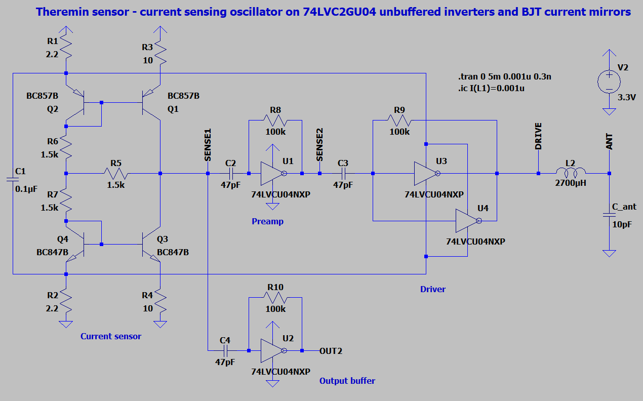
"Eric, do you think it's ok to implement output this way? If so, only two 74LVC2GU04 ICs are needed."

It certainly looks good in simulation, and the circuit is beautiful, but the true test is trying it out, and unfortunately I don't have any LVCU devices on hand.

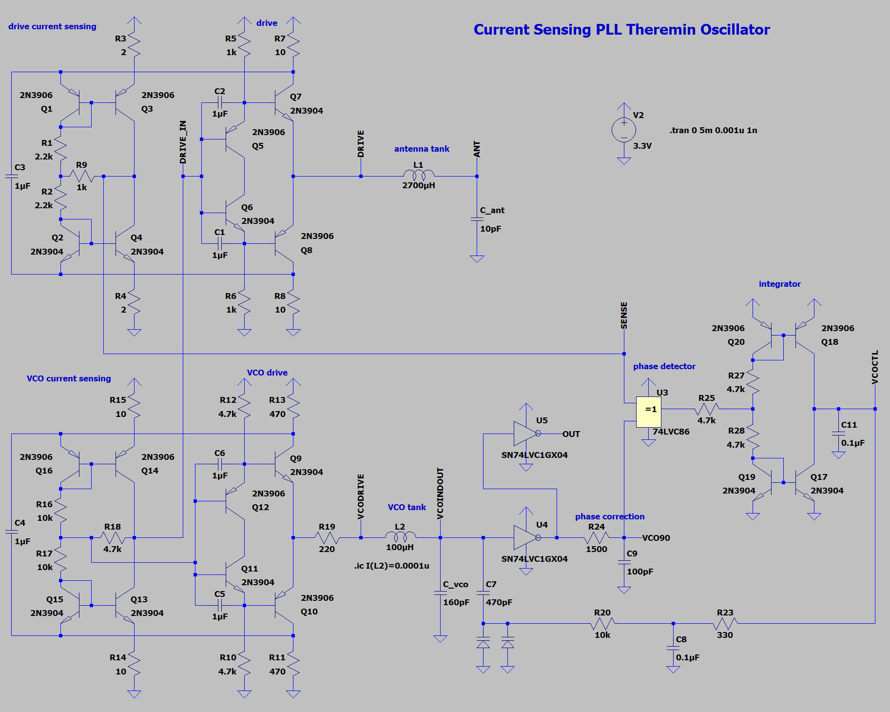
"Oscillator draws ~80mA in this configuration."

I would start to worry about oscillator frequency heating drift with current that high.  It's too bad the oscillator couldn't somehow store the the drive current from one side of the swing and use it for the other, rather than pulling it from VCC / ground.

My next move is to breadboard the 10 transistor active load oscillator to see if it works as well or better than the 8 transistor.  Even though the drive resistor is in series, I think / hope these perhaps offer the best way forward.  The packages may shrink to the size of a flea, but we'll be able to purchase individual transistors for the foreseeable future, and it's probably better to have BJT's rather than CMOS connected to an antennas for ESD reasons.   You're sort of experiencing what I went through looking for logic to "do the right thing" in an analog situation.  I found LVU but then they discontinued it in DIP packaging, so I was forced to switch to AHC, which seems to have much better centered Vt.

I'm not trying to dampen your enthusiasm, but DPLL's still seem to me like the best solution here.  Because phase error is differential and decoupled from frequency, they are essentially feed-forward, so there are no real logic speed issues.  And digital oscillators / phase detectors / phase accumulators have no intrinsic noise to contribute.  And all kinds of environmental noise can be quashed by lowering the loop bandwidth to 100Hz or so.  Someone should make an inexpensive FPGA of some sort that we could use at each antenna.  Do heavy filtering inside it and transfer the operating point back to a processor serially at a 48kHz sample rate.  If the DPLL had a bit of D/A at the output, triangle (rather than square) wave stimulation of the coil could get around a lot of the dither and pin switching speed issues.  True analog mixing / phase detection, or a bit of A/D at the input could get around most aliasing issues.

That said, DPLL's can be difficult to get right, and voltage variations at the various pins can cause trouble.  And I'm convinced that you can make a pro-level Theremin using stable, relatively high voltage analog oscillators.

Posted: 11/12/2021 4:47:58 AM
Buggins

From: Porto, Portugal

Joined: 3/16/2017


I would start to worry about oscillator frequency heating drift with current that high.  It's too bad the oscillator couldn't somehow store the the drive current from one side of the swing and use it for the other, rather than pulling it from VCC / ground.

When inverter is working in pulse mode, energy stored in caps is enough to deal with transition current peak. But if we want to amplify small signal, some other solution for limiting of current is needed.
Older, e.g. HC series, logic has lower power dissipation, but is slower.


I'm not trying to dampen your enthusiasm, but DPLL's still seem to me like the best solution here.  Because phase error is differential and decoupled from frequency, they are essentially feed-forward, so there are no real logic speed issues.  And digital oscillators / phase detectors / phase accumulators have no intrinsic noise to contribute.  And all kinds of environmental noise can be quashed by lowering the loop bandwidth to 100Hz or so.  Someone should make an inexpensive FPGA of some sort that we could use at each antenna.  Do heavy filtering inside it and transfer the operating point back to a processor serially at a 48kHz sample rate.  If the DPLL had a bit of D/A at the output, triangle (rather than square) wave stimulation of the coil could get around a lot of the dither and pin switching speed issues.  True analog mixing / phase detection, or a bit of A/D at the input could get around most aliasing issues.

That said, DPLL's can be difficult to get right, and voltage variations at the various pins can cause trouble.  And I'm convinced that you can make a pro-level Theremin using stable, relatively high voltage analog oscillators.

What do you think about analog PLLs? Would it do the same work as FPGA based digital PLL?
I hope so. I suspect that VCO control voltage will drift (it's obvious solution - read it with ADC). But we still can measure PLL frequency, as with simple oscillator.
I'm looking for possibility to implement simple but powerful PLL.

Currently, my proposal is 20-BJT analog PLL from this post.


In general, PLL requires 2-3 times more components than single oscillator.


So far trying to design good current sensing oscillator.

Combined BJT current sensing + inverter buffer drives tank close to power rails, with configurable (C2) phase error close to 0.
Reduced power consumption comparing to pure inverter based oscillator.
Increased sensitivity allows to reduce R on driver power rails.

Smooth output signal waveform, driven from separate inverter to minimize noise.


450Vpp on antenna, drive current = 13mA


LTSpice model link

Posted: 11/12/2021 2:09:25 PM
dewster

From: Northern NJ, USA

Joined: 2/17/2012

"What do you think about analog PLLs? Would it do the same work as FPGA based digital PLL?"  - Buggins

The biggest drawback of an analog PLL here is probably the introduction of analog noise to the whole LC oscillator construct.  Other than truncation and sampling quantization "noise" digital is completely silent.  Is analog noise a killer?  Probably not, but there is a lot more that you have to get right in the design.  You're kinda making two analog oscillators and comparing them, so the errors and noise can add.

An analog PLL is complex, and could very well be quite layout sensitive.  A DPLL is fairly simple and has no exposed high impedance points or signal delay issues.  A DPLL is entirely repeatable, the exact same thing every time with zero adjustments.

A (non RC) analog PLL has a much more limited tuning range compared to the NCO in a DPLL.  It might not be able to adapt to the full range of environmental C scenarios. 

If the analog PLL VCO control input is highly non-linear then that will be a variable gain factor in the loop.  A DPLL NCO is completely linear.

A DPLL NCO always has perfect 50/50 duty cycle output.

An analog oscillator has to do the right thing every picosecond of its existence, and if some "decisions" by the logic are off in some systematic direction, then they can manifest at a higher level.  The more logic the more decisions are being made, and they can compound internally.  A DPLL can tolerate some noise and the NCO just keeps chugging along, ringing the LC, the combined flywheel of the LC and low loop filter bandwidth create a huge ship that steers very slowly.

This is purely anecdotal, but it may be that the LC DPLL approach has less interaction between the two fields.  Roger pointed out to me that he felt that the D-Lev pitch and volume fields didn't interact at all, as compared the fields of his various analog Theremins.  I haven't experienced any noticeable field interaction on my prototypes, but I haven't tried to quantify (or even qualify) it either, so take that with a grain of salt.

=============

I probably say this too much, but the true test of a Theremin oscillator (including LC DPLL) is how it behaves on the scope at 1/Fmains trigger delay (16.66666ms here in the US) with various coils and antennas attached.  10ns or so of high frequency phase noise is OK, but if it is jumping around much beyond that, particularly if it is doing so at some random / low frequency rate that can't be low pass filtered, then it is probably unusable because those jumps will show up in the far field (or worse).  It's too bad that Spice can't reveal this type of go/no go behavior.

Posted: 11/12/2021 7:47:55 PM
Buggins

From: Porto, Portugal

Joined: 3/16/2017

Interesting.
We still don't know the source of noise, and how low frequency signal like 60Hz main hum may modulate 1MHz oscillator frequency.
If most of noise is received by antenna, having additional LC oscillator (VCO) which is not connected to antenna could improve stability and reduce noise.
I will continue to search for analog PLL solution - until simple one is found - to test on real hardware.
If analog PLL was good enough, MCU theremin may have the same quality of sensors as FPGA one.

I'm going to design and order PCBs for several types of oscillators - to compare.
I don't have scope with trigger delay, but it's possible to collect data by MCU, and then process it to see noise level.
It's very bad that we cannot realistically simulate noise in spice model.  

Posted: 11/13/2021 3:40:31 AM
dewster

From: Northern NJ, USA

Joined: 2/17/2012

"We still don't know the source of noise, and how low frequency signal like 60Hz main hum may modulate 1MHz oscillator frequency." - Buggins

True.  You can replace the antenna with a capacitor and look at the noise level there, but it maybe doesn't tell you a whole lot about how it behaves when a more complex impedance & source of noise / hum is connected.

"I don't have scope with trigger delay"

You're feeling your way in the dark without one.  With one you can usually very quickly determine whether a particular oscillator is worth pursuing further or not.  They don't cost much anymore but they are priceless when doing this sort of research.  A breadboard and a scope are your bread and butter.

Your MCU project has a lot of merit.  Even if you just improved on the Open.Theremin a little (somewhat higher voltage fields & more computing horsepower) it would help folks out enormously.  Moog Inc. seems to be giving up.

Posted: 11/13/2021 6:36:23 PM
Buggins

From: Porto, Portugal

Joined: 3/16/2017

Your MCU project has a lot of merit.  Even if you just improved on the Open.Theremin a little (somewhat higher voltage fields & more computing horsepower) it would help folks out enormously.  Moog Inc. seems to be giving up.

Teensy 4 MCU has x1000 more computing power than Open.Theremin Arduino UNO.
Sensor approach with direct measurement of oscillator frequency with timer captures + DMA should be better, too.
I hope my MCU project may easy become next get Open.Theremin.

Regarding noise simulation. If main hum comes from environment and mostly received by antenna, what about replacing ground point of C_ant with virtual noisy ground - small 60Hz sine (or 60Hz + harmonics). As well, we can replace power supply with noisy one.
Oscillator noise sensitivity may be measured by checking of output signal FFT. Model immune to both power line and antenna noise most likely would be good in reality.

Eric, do you have examples of better and worse oscillators - based on delayed trigger scope?
We can take several oscillator models, add noise and check output spectrum - if modelled noise level correlates with experimental findings - noise simulation method makes sense in future good oscillator design attempts.

As well, possible source of noise could be input pin schematic of FPGA/MCU. In general, it's similar to comparator, comparing input voltage with some threshold (with small hysteresys). Noise from supply voltage effectively shift I/O buffer threshold value. This offset moves detected edge.
Such type of noise injection is sensitive to sensor ouput signal slew rate. Low slew rate causes bigger influence of power rail noise, while sharper edge is less sensitive to it.
Using of differential signal for interfacing between sensor and FPGA would almost eliminate power rail noise effect - input circuit will compare two input signals, instead of one single ended signal with noisy threshold point.
Does your FPGA support differential pairs for I/O?


Posted: 11/14/2021 4:26:08 PM
dewster

From: Northern NJ, USA

Joined: 2/17/2012

"Teensy 4 MCU has x1000 more computing power than Open.Theremin Arduino UNO.  Sensor approach with direct measurement of oscillator frequency with timer captures + DMA should be better, too.  I hope my MCU project may easy become next get Open.Theremin." - Buggins

I think your project is in a great position to do that.  You're researching the basics to death, which is a good thing as long as it doesn't burn you out.

"Regarding noise simulation. If main hum comes from environment and mostly received by antenna, what about replacing ground point of C_ant with virtual noisy ground - small 60Hz sine (or 60Hz + harmonics). As well, we can replace power supply with noisy one.  Oscillator noise sensitivity may be measured by checking of output signal FFT. Model immune to both power line and antenna noise most likely would be good in reality."

That sounds good, but FFT might not be the best at revealing and quantifying jitter / jumping behavior.  And you might need several seconds of sim data, which could take forever.

"Eric, do you have examples of better and worse oscillators - based on delayed trigger scope?"

Worse and worser! ;-)  I'm trying to make some movies from my scope to show you.  The data of each trace can be saved digitally, but I can't find a way to turn it into a movie.  Webcam capture via my Linux box is blurry.  My digital camera gives the best results and I'll try to snag some examples soon.

"We can take several oscillator models, add noise and check output spectrum - if modelled noise level correlates with experimental findings - noise simulation method makes sense in future good oscillator design attempts.  As well, possible source of noise could be input pin schematic of FPGA/MCU. In general, it's similar to comparator, comparing input voltage with some threshold (with small hysteresys). Noise from supply voltage effectively shift I/O buffer threshold value. This offset moves detected edge.  Such type of noise injection is sensitive to sensor ouput signal slew rate. Low slew rate causes bigger influence of power rail noise, while sharper edge is less sensitive to it.  Using of differential signal for interfacing between sensor and FPGA would almost eliminate power rail noise effect - input circuit will compare two input signals, instead of one single ended signal with noisy threshold point.  Does your FPGA support differential pairs for I/O?"

The D-Lev does experience FPGA pin movement influencing the pitch field DPLL.  Rhythmic current slugs from the audio generation and processing can cause some variation in VCC.  It's really bad when the supply voltage is too low for the FPGA LDO to regulate to 3.3V (shouldn't happen but can with poor USB connections and thin dongle wires).  Whatever remains is effectively masked by the 8th order tracking lowpass filter 1 octave below the output pitch.  So I consider it to be a solved issue.  The FPGA I/O can do differential pairs, but unfortunately not when the bank supply voltage is 3.3V (I researched this).

It would be really great to isolate each field generation / acquisition LC DPLL from the rest of the processing going on.  Hardware doesn't cost all that much compared to cabinetry and such, and FPGAs can look pretty simple on the outside.  I guess the question is when do you stop seeking diminishing returns?

Posted: 11/15/2021 2:47:42 PM
dewster

From: Northern NJ, USA

Joined: 2/17/2012

Vadim, another issue that occurred to me is simultaneous "switching" of logic on the same IC die.  The D-Lev AFE uses a hex inverter, and I've noticed that the in-phase transitions cause ripples on the quadrature wave and vice versa.  Using quadrature phase sensing really helps here as it gets the all important edges as far away as possible from the other side's edges.  Anyway, this is one more source of "noise" that you won't see in simulation but can certainly perturb things.

I also have a bit of mildly surprising data re. your recent oscillators.  Using your single inverter followed by 5 in parallel, a 3.8mH coil, and a license plate sized aluminum plate antenna:

With LVU I'm seeing a supply current of 16mA / 220Vpp at the antenna.

With AHC I'm seeing 4mA / 320Vpp.

With the 8 transistor oscillator I'm seeing 6.5mA / 160Vpp (though some of the current is the 3.3V regulator).

The very small AHC supply current was the surprise for me.  Lots of high speed edge ringing, but the phase looks really well centered in the drive signal.

Posted: 11/16/2021 6:14:06 PM
Buggins

From: Porto, Portugal

Joined: 3/16/2017


Vadim, another issue that occurred to me is simultaneous "switching" of logic on the same IC die.  The D-Lev AFE uses a hex inverter, and I've noticed that the in-phase transitions cause ripples on the quadrature wave and vice versa.  Using quadrature phase sensing really helps here as it gets the all important edges as far away as possible from the other side's edges.  Anyway, this is one more source of "noise" that you won't see in simulation but can certainly perturb things.


Yes, it might be a problem for current sensing PLL front end, if not handled correctly.
At least, we can use small logic ICs, 6-pin single or dual inverters (74..1G or 2G).

I also have a bit of mildly surprising data re. your recent oscillators.  Using your single inverter followed by 5 in parallel, a 3.8mH coil, and a license plate sized aluminum plate antenna:

With LVU I'm seeing a supply current of 16mA / 220Vpp at the antenna.

With AHC I'm seeing 4mA / 320Vpp.

With the 8 transistor oscillator I'm seeing 6.5mA / 160Vpp (though some of the current is the 3.3V regulator).

The very small AHC supply current was the surprise for me.  Lots of high speed edge ringing, but the phase looks really well centered in the drive signal.

Unbuffered inverters consume max current when input is far from rail.
For sharp edges, big current peaks are only at edges, which can be mostly smoothed by capacitor.
In buffered inverter, input stage consumes relatively low current with input at VCC/2, and internal and output inverters are working with sharp edges (only have peaks at edges).

But in the middle of cycle, inverters sinks/sources current to/from LC tank. I would expect tank current reflected in power consumption.
Tank driven from energy saved in capacitor?


Idea regarding testing of main hum noise in LTSpice.
We can take several screenshots at different time positions, and combine them in some graphics editor (semitransparent layers).

What about using separate FPGA for each sensor axis?

LCMXO2 looks fine enough.
At arrow.com LCMXO2-1200HC-4SG32C costs $5.435
(although it's out of stock on many other sites)
Tiny QFN32 looks easy enough for soldering. 22 I/O should be enough.

It looks like there is some hardware support for high speed I/O SERDES.
LVDS differential interface support allows to reduce noise between FPGA and analog frontend.
22 I/O pins should be enough for both PLL side and main board interfacing.

1200 LUTs should be enough for good DPLL with filter.
FPGA can be programmed from main board (MCU or big FPGA), or one using programming cable - since Mach XO2 is non-volatile and has internal flash for configuration.

Main board may control sensor FPGAs via SPI (various settings).
Sensor value may be read using SPI as well.
But to limit main board resource usage, we can use I2S for reading axis values from sensors.
Sensors may send axis values as I2S data (left for one axis, right for another).


Posted: 11/17/2021 2:36:26 PM
dewster

From: Northern NJ, USA

Joined: 2/17/2012

"But in the middle of cycle, inverters sinks/sources current to/from LC tank. I would expect tank current reflected in power consumption.  Tank driven from energy saved in capacitor?"  - Buggins

Maybe it's my DMM?  I don't entirely understand it either.

"What about using separate FPGA for each sensor axis?  LCMXO2 looks fine enough. At arrow.com LCMXO2-1200HC-4SG32C costs $5.435  Tiny QFN32 looks easy enough for soldering. 22 I/O should be enough.  It looks like there is some hardware support for high speed I/O SERDES.  LVDS differential interface support allows to reduce noise between FPGA and analog frontend.  22 I/O pins should be enough for both PLL side and main board interfacing.  1200 LUTs should be enough for good DPLL with filter."

That does look like a possible candidate, thanks for researching it!  I'm downloading the "Diamond" tooling to see if it works in Linux Mint.  IIRC I used an XO part in the past (long ago).

"Main board may control sensor FPGAs via SPI (various settings).  Sensor value may be read using SPI as well.  But to limit main board resource usage, we can use I2S for reading axis values from sensors.  Sensors may send axis values as I2S data (left for one axis, right for another)."

I think it would need to be a bi-directional serial interface, like SPI, so you can set things like dither strength.  For portability (and because I'm a control freak) I prefer to write my own interfaces in SV rather than use hard coded logic blocks.  Then you can do anything as long as both ends agree on the protocol.

Moving functionality off of the main FPGA would require some thought as to timing and synchronization.  When you've got a single clock inside a single FPGA everything can be fairly straightforward (if you have enough internal PLLs).

Vadim, the world seems to be crying out for a solid, full-featured, inexpensive Theremin, which you and I know is clearly doable with current technology.  I think FPGA-based LC DPLLs coupled to a cheap multi-core processor, with a touchscreen rather than encoders, might be the best way to go.  I hate to lash anything to the shifting sands of consumer computational solutions, but a cheap 7" tablet running an app comes to mind (otherwise one is re-inventing the wheel to some degree - though often that wheel could use some re-inventing, if only for increased control).  I'd really like to contribute to such a project, I'd certainly be up for porting all of my D-Lev code to it.

You must be logged in to post a reply. Please log in or register for a new account.