Armstrong, Hartley, Colpitts, Clapp, Wallin...

Posted: 3/19/2023 12:30:28 AM
Buggins

From: Porto, Portugal

Joined: 3/16/2017


Very interesting topic.  I would have viewed it sooner but it sounded like a law firm with a lot of partners......

Ahahahah.
I thought these names look familiar for everyone who is looking for LC oscillator.
Unfortunately I cannot rename the topic to make it less confusing.
BTW, is current sensing based oscillator - a new kind of oscillators, and a real invention made by Eric? I still did not get an answer...

Vadim, thank you for posting your fascinating findings and sims!  I'm a bit underwater at the moment but plan to play with your designs shortly.  Your inverter version is the one to beat, truly an outstanding oscillator!

Eric, I hope you will check some of them on breadboard
I like playing with LTSpice, but don't have a breadboard, components, scope anymore after moving to Porto.
I tried to play with inverters and opamps as drive buffer, and found that it's hard to get them working stable.
So now I think having your 4-bjt buffer on emitter followers is probably the best option.

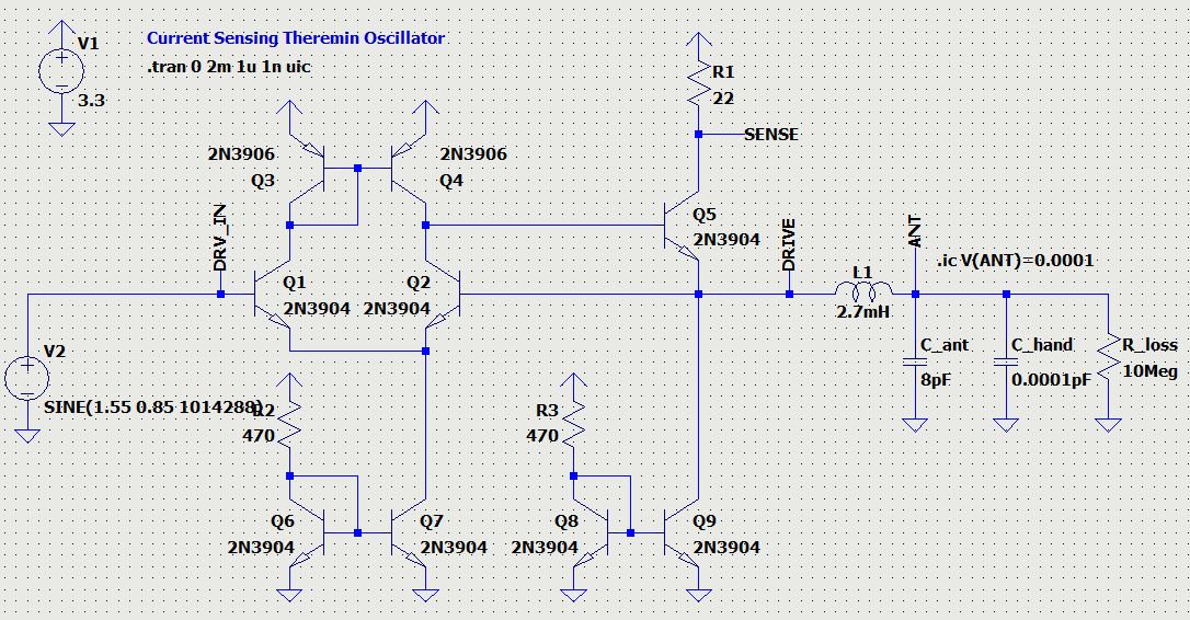
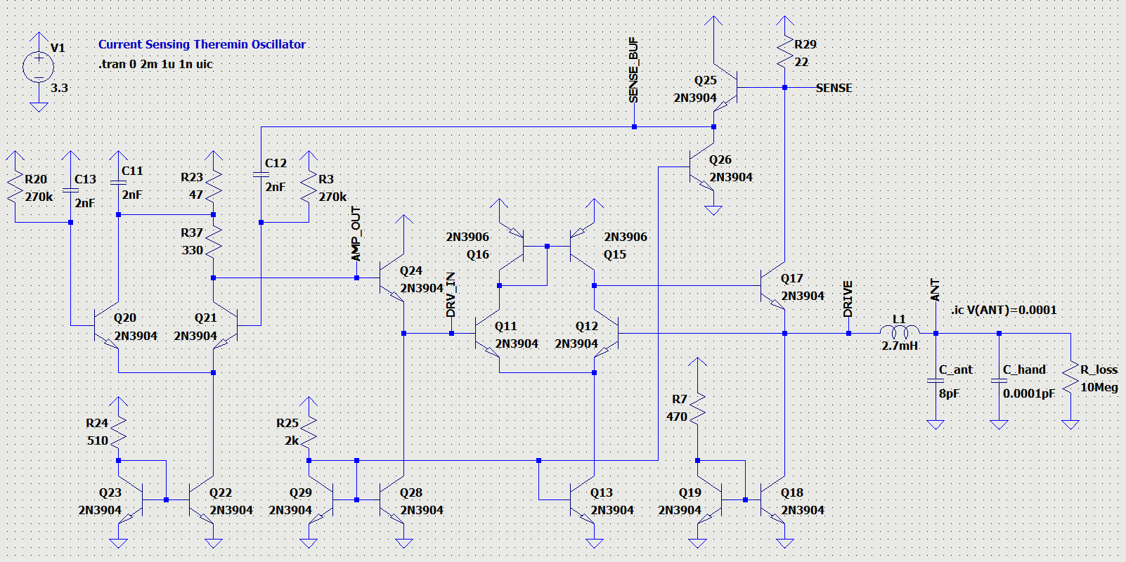
I've combined two recent schematics I've posted here. 10 BJTs. (LTSpice model link to play with)


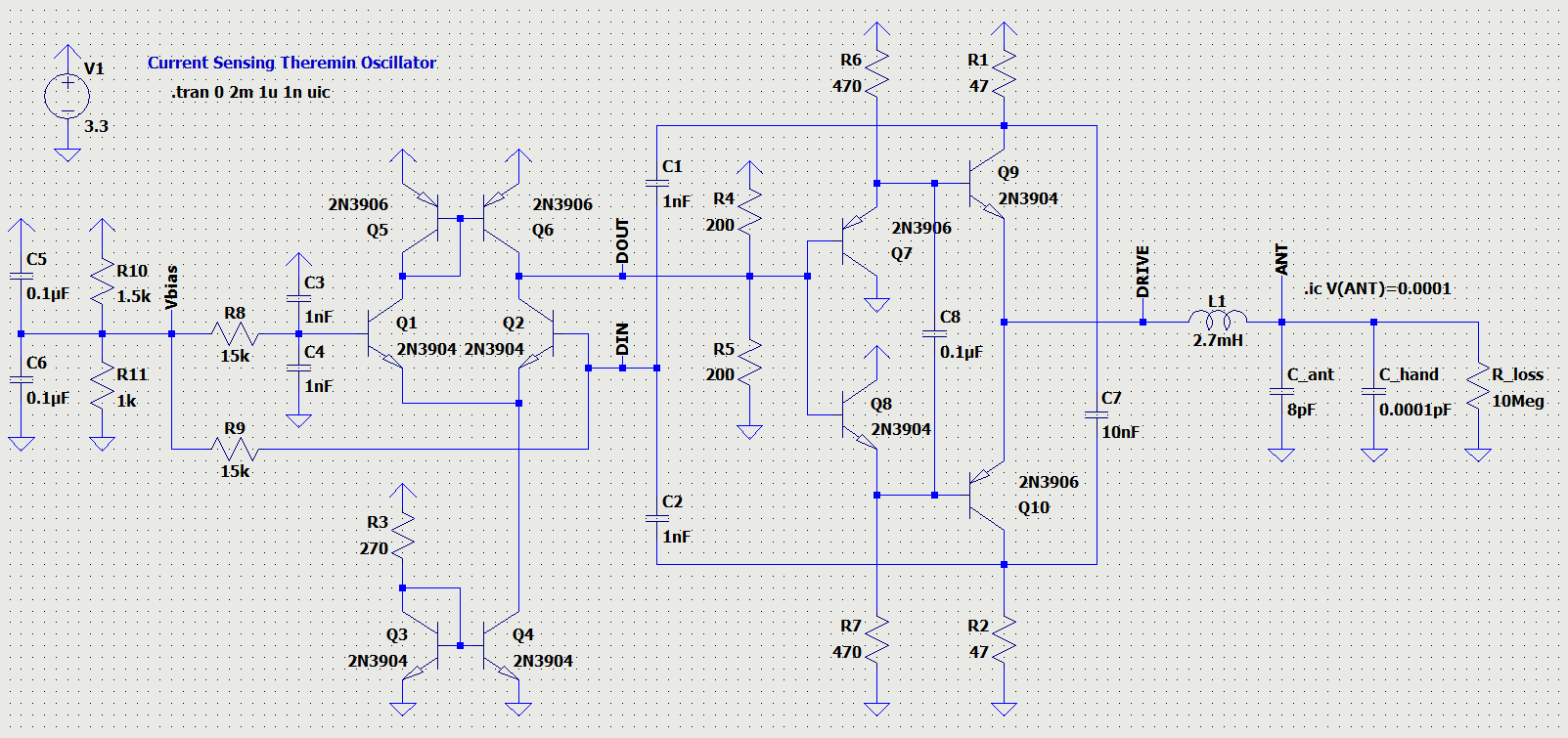
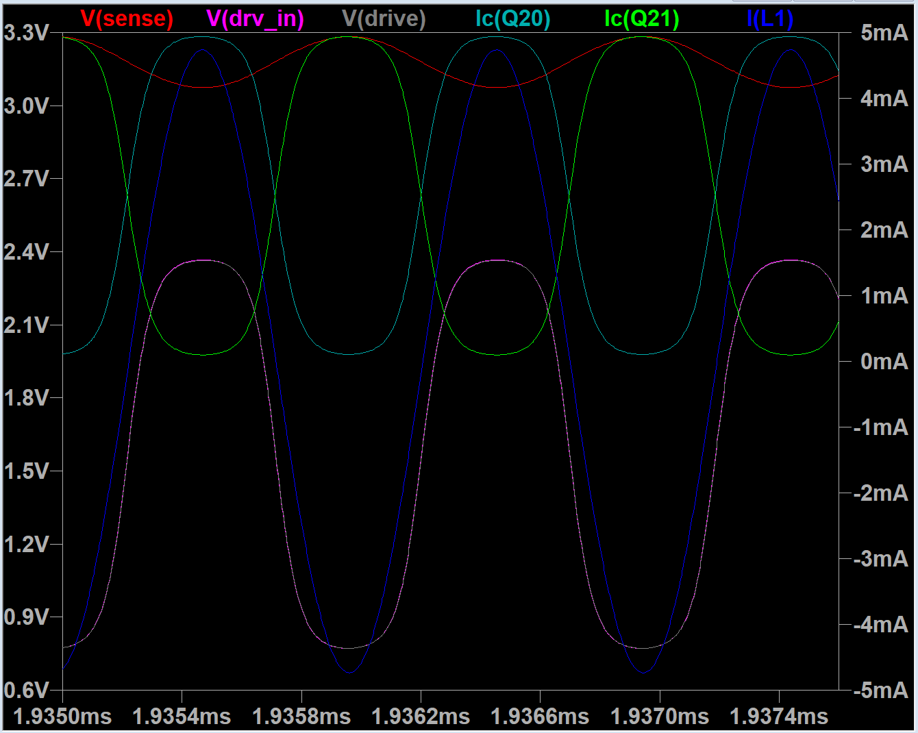
Diff amplifier uses current mirror load, and its current output is converted to voltage on a resistor divider.
I've tried to tune this oscillator to minimize phase error and maximize antenna voltage swing.
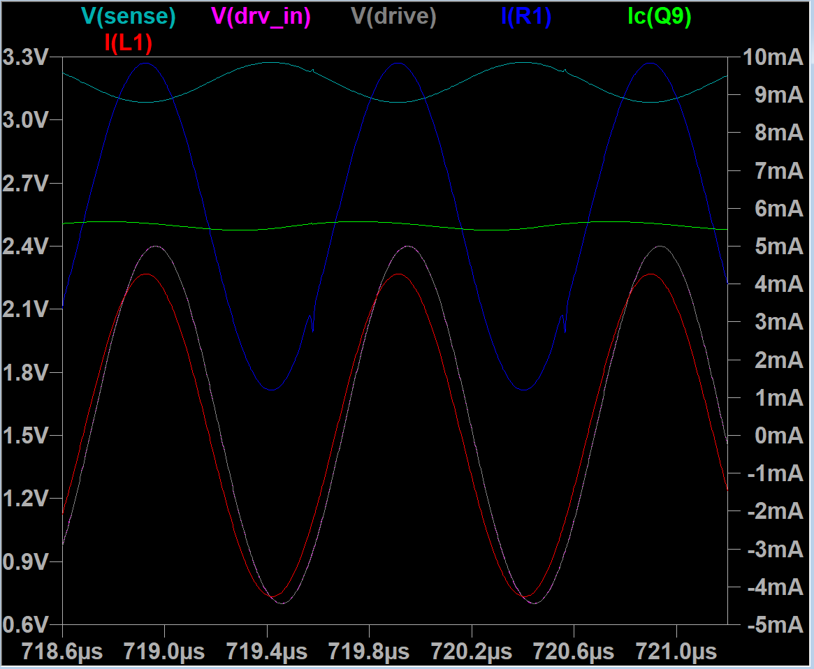
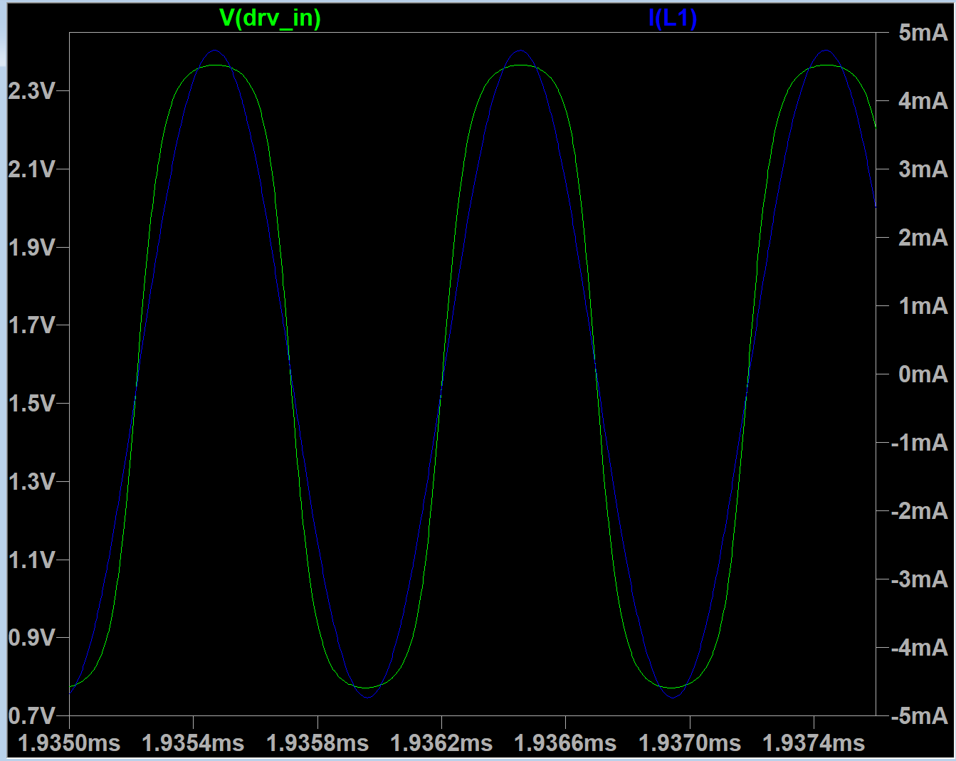
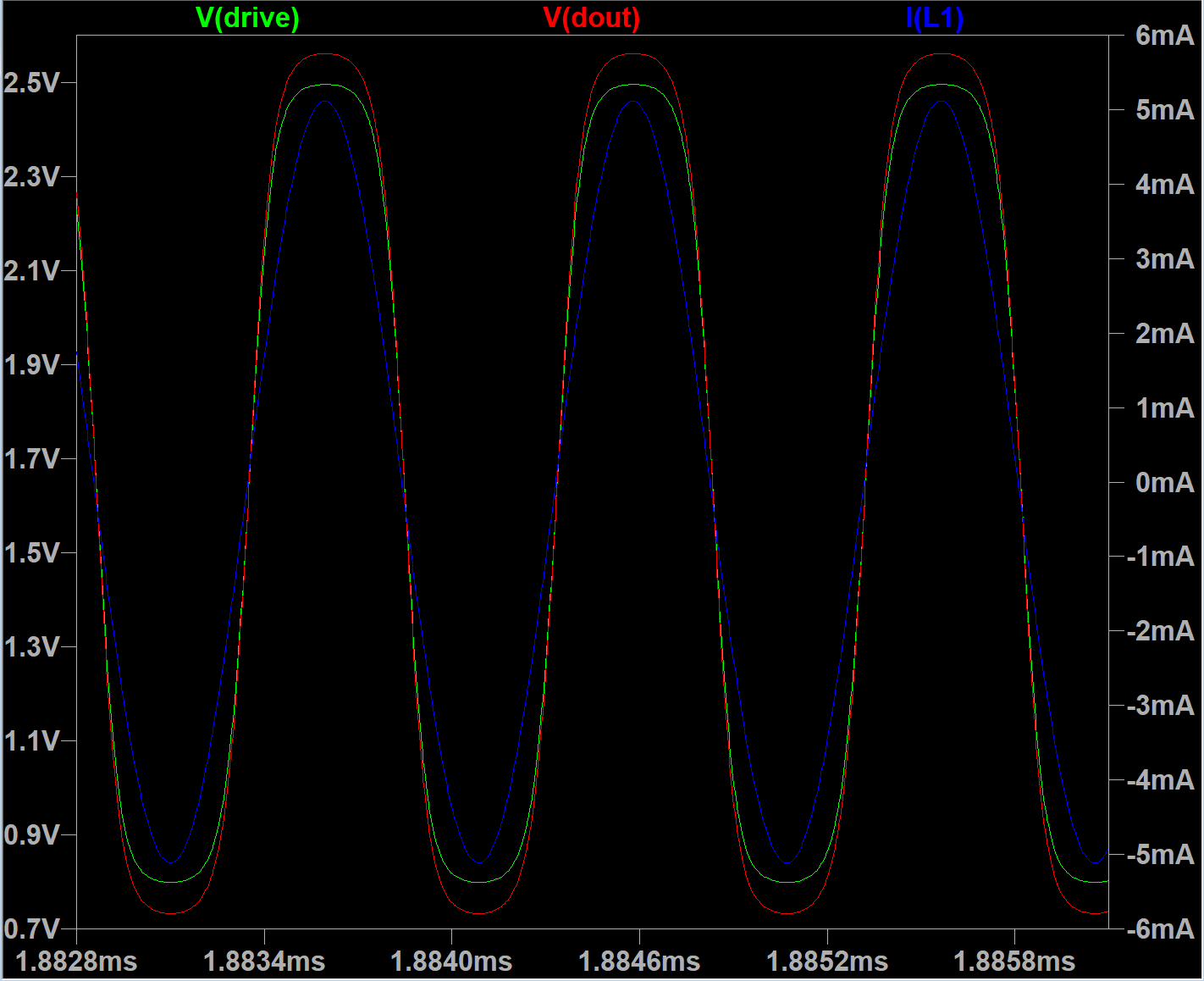
I've managed to get nice smooth symmetric sine-like drive signal with 6-7ns phase error.
BTW, delay from 4-BJT output cascade is only ~400ps...


The price for now delay is high power consumption (~35mA).

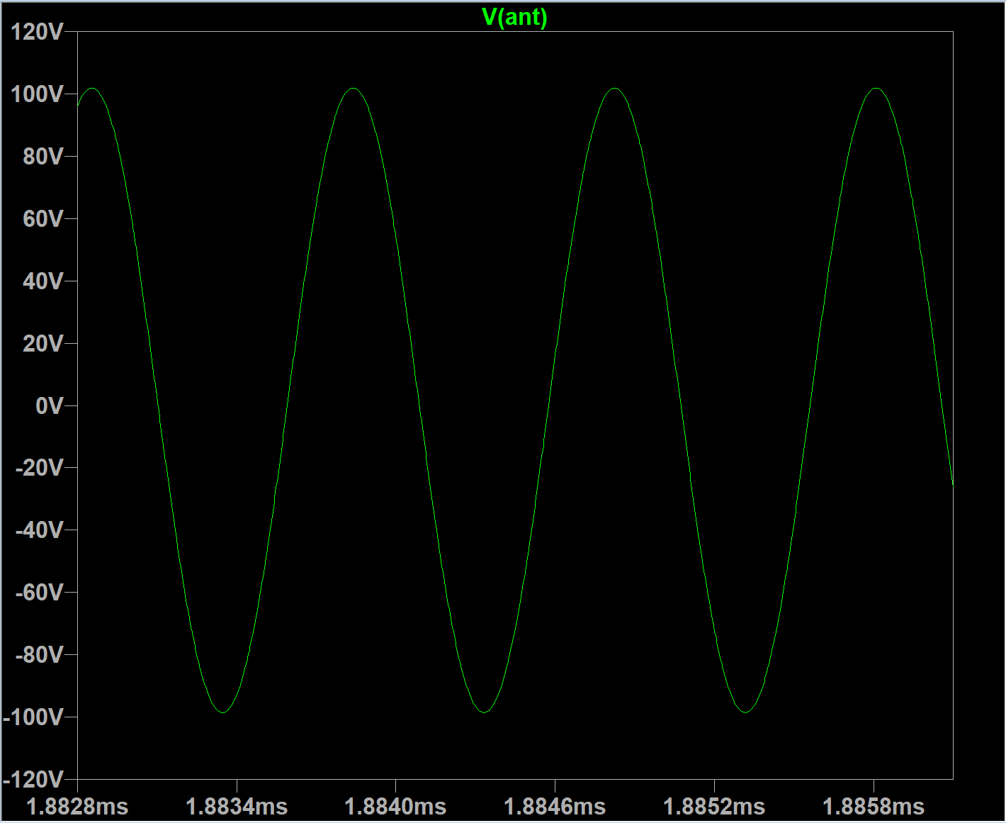
Drive swing is 1.7V. It feeds LC tank with 5mA, giving ~200V voltage swing on antenna.

Main concern is still a behavior of oscillator when hand touches the antenna.


Posted: 3/19/2023 2:30:35 AM
Yngvox Moogsteen

From: The Middle

Joined: 9/23/2021

Very interesting topic.  I would have viewed it sooner but it sounded like a law firm with a lot of partners......Ahahahah.I thought these names look familiar for everyone who is looking for LC oscillator.Unfortunately I cannot rename the topic to make it less confusing.

Just kidding around.  It really is a pleasure and honor to read you and Dewster go back and forth and The knowledge gained is appreciated.  To be exposed to open dialogue between top experts of a field developing theories and practical applications ,
“D-LEV”, 
is inspirational...

Thanks to all at Theremin World, especially Jason.

Posted: 3/19/2023 7:22:01 AM
dewster

From: Northern NJ, USA

Joined: 2/17/2012

"I would have viewed it sooner but it sounded like a law firm with a lot of partners......"  - Yngvox Moogsteen

Dewster, Cheatem & Howe ;-)

Posted: 3/22/2023 12:17:29 PM
Buggins

From: Porto, Portugal

Joined: 3/16/2017

Yet another attempt to design a good current sensing based ("wallin") oscillator.
Good oscillator should have small phase error, high voltage swing, nice smooth drive waveform.
Current sensing approach looks as a best one for me. I think it should have low noise level (noise from antenna is filtered out by LC tank) and high sensitivity - the only C of LC tank is antenna + hand.

Found interesting differential cascade based voltage follower cirquit, as a good current sensing output cascade.
It's in "precise voltage follower" section on "Differential cascade" wiki page, but it does not have English version.

But I believe it can be google-translated.

It's fast (<< 0.1ns) and precise. Keeps output voltage matching to input while inputs and outputs are in working range (0.5..VCC-0.9) and current of output cascade is big enough.
Differential cascade compares voltages on input and output and control emitter follower to keep output voltage equal to input.
Easy to add gain - by adding voltage divider in output voltage sensing part.
Easy to measure output current - e.g. by putting shunt resistor to output cascade emitter follower transistor power rail.
Although this cascade can easy amplify input, and voltage on sensing resistor can be amplified by this cascade itself, I have not figured out how to implement smooth limiter on it.
So, if you try to make an oscillator working only on this buffer, drive signal becomes distorted after output voltage starts exceeding the working range, and delay grows.

Voltage follower on diff amp as output stage of current sensing theremin oscillator.
LTSpice model link to play with.

Max working range: 1.9Vpp with 1.55V center point (0.7V .. 2.4V)

With 4.25 mA 1.9Vpp sine drive, it gives 165Vpp on antenna.

Buffer latency depends on differential cascade current - the bigger current is, the faster buffer you get.
Diff cascade 1mA  - 1.2ns delay
Diff cascade 2.6mA - 0.55ns delay
Diff cascade 5.5mA - 0.275ns delay

Sensing shunt resistor eats part of working range - about 0.25V in this configuration.

Making oscillator based on this buffer.

Ok, let's add one more differential cascade, as limiting amplifier for current sensing.
This schematic looks a bit overcomplicated, has 17 BJTs.
According to simulation it should work fine.
Github link to LTSpice model.


Drive is 1.6Vpp symmetric sine-like 4.7mA.

Small 4ns phase error.


180Vpp on antenna.

Voltage on shunt resistor, currents in sensing amplifier diff cascade, voltage on sensing amplifier output and drive signal:
(Just a nice tech porn)

Still trying to find a better schematic.
This one has acceptable low phase error and nice shaped drive.
But its drive signal range (and hence the voltage swing on antenna) is limited, and the design is a bit complicated.

The best possible output buffer should have common emitter transistor drive on both of rails to get output range close to power rails.
Probably, current mirror like drive on both rails should resolve it.
Differential cascade should be used to control output voltage waveform.
Some good and natural way is needed for output current measurement. Is it possible to get it in some natural way avoiding shunt resistor which reduces drive range?
Will continue to play with LTSpice.

Posted: 4/4/2023 9:47:42 AM
Buggins

From: Porto, Portugal

Joined: 3/16/2017

Interesting approach for building of current sensing output buffer - transconductance amplifier.
OTA - is differential voltage input current output amplifier. Usually based on differential cascade + current mirrors.
When used in voltage follower mode - can work as output buffer for driving of LC tank.
Additional current output may provide a copy of current fed into output to keep waveform close to input one.
Push-pull output can provide output range close to power rails (0.3V or even less from rails).
Delays between input and output, and LC tank current and SENSE output are pretty small.
Can be turned into oscillator by feeding of SENSE to DRIVE_IN, but only after some limiter cirquit - otherwise it will work nice on start, but will behave worse once voltages/currents exceed limits.
We can use additional differencial cascade as a low delay limiter producing nice waveform something average between sine and square.

LTSpice model is available on Github


This buffer works perfect while does not exceed input and output ranges.
Input range is about 1.6Vpp if centered at 1.65V - in voltage follower (Gain=1) mode.
It's possible to extend output voltage range to ~0.3V .. VCC-0.3V -- by introducing gain - just divide output voltage before comparing.
Simple resistive divider makes the cirquit less stable, and affects current sensing precision (because output current is being consumed not only by LC tank, but as well by divider).
Some low delay active solution with Gain=0.3..0.5 is needed.

Antenna swing and LC tank current:

Drive input and output voltages:

LC tank current and SENSE output:

There are some OTA ICs available (e.g. LM13700 NE5517 OPA615 OPA860 OPA861), but all of them cannot be driven by 3.3V
As well, it's impossible to add an copy current output (unless second IC is used to do it).
OTA ICs in general are pretty close to my schematic, but have more complex current mirrors, and have diodes with separate bias input on input - for linearization purposes.

Posted: 5/9/2023 9:54:26 AM
Buggins

From: Porto, Portugal

Joined: 3/16/2017

Trying to ask ChatGPT about oscillators.
Found that naming "wallin oscillator" is already occupied...
It has been invented in 1955!

Q: How does current sensing LC oscillator work

A current-sensing LC oscillator is a type of LC oscillator that uses a current-sensing element to generate an oscillating signal. In this circuit, the inductor (L) is connected in series with a sensing resistor (Rs) and a capacitor (C). The sensing resistor is used to measure the current flowing through the inductor. The output of the sensing resistor is connected to the input of a transconductance amplifier, which provides the necessary gain to sustain the oscillation.

The basic operation of a current-sensing LC oscillator is as follows:

1. Initial Conditions: Assume that there is a small initial current flowing through the inductor and capacitor, and no current is flowing through the sensing resistor.

2. Charging of the capacitor: The capacitor starts to charge through the inductor, creating a magnetic field around the inductor.

3. Current sensing: As the current flows through the inductor, a voltage drop develops across the sensing resistor. This voltage is proportional to the current flowing through the inductor.

4. Amplification: The voltage signal from the sensing resistor is amplified by the transconductance amplifier and fed back to the input of the LC circuit.

5. Oscillation: The feedback causes the circuit to oscillate at the resonant frequency of the LC circuit. The oscillation produces a sinusoidal waveform across the capacitor, with the amplitude determined by the feedback gain.

6. Continuation: The oscillation continues, with the energy of the magnetic field in the inductor being transferred back and forth between the capacitor and inductor.

7. Regulation: The amplitude of the oscillation is regulated by the feedback gain, which is determined by the transconductance of the amplifier and the value of the sensing resistor.

The current-sensing LC oscillator has some advantages over voltage-controlled oscillators (VCOs). It is less sensitive to variations in the power supply voltage, as the current flowing through the inductor is more stable than the voltage across the capacitor. Additionally, current sensing can be used in some applications where voltage sensing is not possible or desirable.

Q: what is wallin oscillator

The Wallin oscillator is a type of LC oscillator that uses a transformer to provide positive feedback to the LC tank circuit. It was first proposed by E.B. Wallin in 1955 as a modification of the Colpitts oscillator.

The basic circuit of the Wallin oscillator consists of an LC tank circuit connected in series with a transformer. One end of the transformer primary is connected to the collector of a bipolar junction transistor (BJT), while the other end is connected to ground. The emitter of the BJT is connected to ground, and the base is connected to the junction of the inductor and capacitor in the LC tank circuit. A resistor is connected between the base and ground to bias the BJT.

When the oscillator is initially turned on, a small current flows through the inductor and capacitor, creating a magnetic field in the transformer. The transformer provides positive feedback to the LC tank circuit, causing it to oscillate at its resonant frequency. The feedback voltage from the transformer is amplified by the transistor, providing the necessary gain to sustain the oscillation.

The Wallin oscillator has some advantages over other LC oscillators. It is less sensitive to variations in the power supply voltage and temperature because the transformer provides a more stable feedback signal than a simple voltage divider. Additionally, the transformer can be used to match the impedance of the LC tank circuit to the output impedance of the transistor, improving the efficiency of the oscillator.

However, the Wallin oscillator also has some limitations. The use of a transformer can introduce additional parasitic capacitance and inductance, which can affect the frequency stability and phase noise performance of the oscillator. Additionally, the transformer can be sensitive to mechanical vibration and shock, which can affect the oscillator's performance.

But I tried to google about wallin oscillators and the only link is this thread.
So, it seems chatGPT is hallucinating. Should be E.D.Wallin, not E.B.Wallin

Posted: 5/9/2023 12:50:30 PM
dewster

From: Northern NJ, USA

Joined: 2/17/2012

That's hilarious Vadim!  LLMs are almost comically over eager to give a response, any response, and seem to suffer from not knowing what they don't know.

You must be logged in to post a reply. Please log in or register for a new account.