


Trying to figure out what's going wrong with my power circuit for the theremin described here. Simple circuit that takes 12VAC to make a dual polarity 12VDC supply. The points which should measure +16 and -16 read +-17.5V instead, but I assumed that was because of no load. The positive output generates about 11.8V, which is fine, but the negative output generates -.6V instead of -12. My power supply is a Jameco ADU120200 which is 12VAC and 2A and I'm using one of those little wiring harnesses that plugs on to the adapter. I am absolutely positive that my circuit is correct, I've built it with different organizations, spread out, clumped, on a breadboard, on a prototyping board, all to the same result. What am I doing wrong??
I also noticed that the LM78L12 pinout on the schematic from Moog doesn't match the datasheet, IN/OUT are flipped compared to the official datasheet from TI. Didn't try it with Moog's pinout, as I'm fairly certain that would blow up one of those massive 2200uF caps.

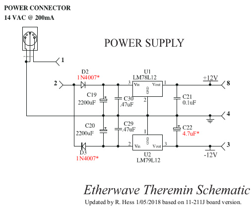
 id you by any chance not notice the negative regulator is a different part number than the positive regulator? LM79L12 (neg) LM78L12 (pos).Regulators can oscillate, small capacitors very near the pins are often specified in the spec sheets. Sometimes they are sensitive to output capacitor ESR and require a higher ESR type, like tantalum.
