Let's Design and Build a (mostly) Digital Theremin!

Posted: 3/25/2024 12:12:30 PM
dewster

From: Northern NJ, USA

Joined: 2/17/2012

TCOIL HELP

Here's the tcoil help screen:

Code:
Usage: TCOIL_EXE [ command ] [ -flag [option] -flag [option] ... ]

COMMANDS & FLAGS:

  [command] -h                                              Help with individual command flags
  help  [-v]                                                Command line help with optional examples

  wire [-awg gauge] [-wcd wire ID mm] [-b build]            Wire specs
  lcf [-l mH] [-c pF] [-f kHz] [-r Ohms]                    Given 2 of LCF, solve for the 3rd
  pvc [-i]                                                  PVC tubing table

  brooks 
  • ...                                            Solve brooks coil   solenoid
  • ...                                          Solve single layer solenoid   donut
  • ...                                             Solve multi layer donut   choke
  • ...                                             Solve multi donut choke   xfmr
  • ...                                              Solve transformer (given N, N2 turns only)     
  • [-file file] [-wd wire OD mm] [-wcd CU dia mm]           commands: choke, donut, solenoid, brooks, xfmr    [-f khz] [-c pF]                                         commands: choke, donut, solenoid, brooks    [-fd form dia mm]                                        commands: choke, donut, solenoid, xfmr    [-ow donut width turns]                                  commands: choke, donut, xfmr    [-oo donuts offset mm]                                   commands: choke, xfmr    [-o donuts]                                              commands: choke    [-wd2 mm] [-wcd2 mm] [-fd2 mm] [-ow2 turns] [-n2 turns]  commands: xfmr    [-l mH]                                                  Solve given L    [-n turns]                                               Solve given N turns    [-wl m]                                                  Solve given wire length

    And of course it got all munged up because the posting tool hates the greater and less than symbols, so I replaced them here with [].  The posting tool is giving me an error when I post, but the post itself happens OK.

    Posted: 3/28/2024 9:18:12 PM
    dewster

    From: Northern NJ, USA

    Joined: 2/17/2012

    A Tale Of Three Coils

    Giving my coil design program something to do:

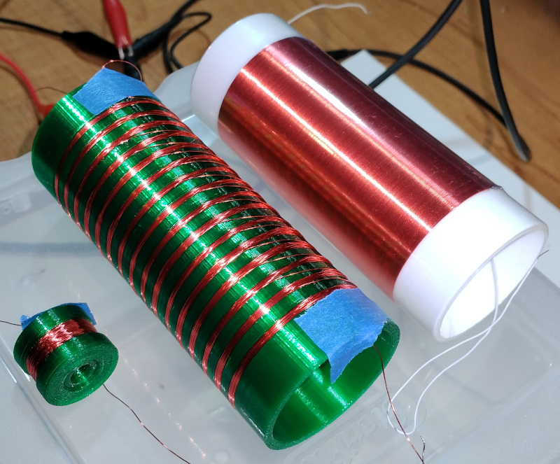
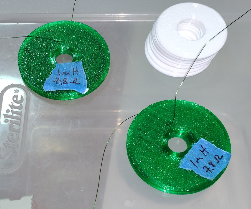
    Coil on the right is the usual 1 mH / 10.6 DCR single layer solenoid on 38 mm dia PVC plumbing in the D-Lev kit.
    Coil on the left is a 1 mH / 4.4 DCR Brooks on a PETG printed bobbin.
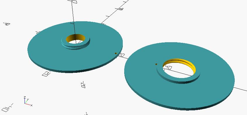
    Coil in the middle is a 1 mH / 10.4 DCR 16 donut choke with 15.6 turns per donut, on a PETG form with similar dimensions to the solenoid.

    All wound with Remington AWG 30 single coat wire.

    Observations:

    1. Free air resonance for the solenoid is 3.14 MHz, for the choke 2.46 MHz.  As expected, the Brooks coil is a total dud for Theremin field coil use - I couldn't even find its free air resonance.

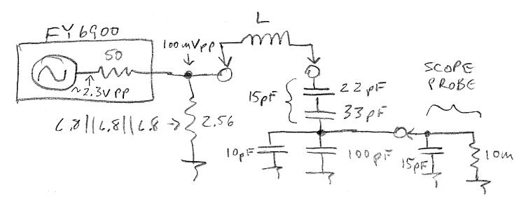
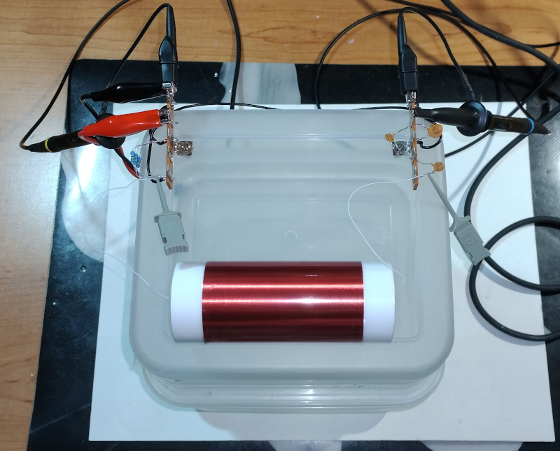
    2. The choke clearly has somewhat lower Q than the solenoid, with the kit pitch plate of ~12 pF I measure Q=50 for the choke and Q=75 for the solenoid.  This is a really rough measurement that doesn't take into account 50 Ohm drive droop at resonance, the real Qs are almost certainly higher.  But the lower free air resonance is consistent with lower Q.

    3. I have some AWG 32 double coat that might improve the choke Q by reducing the proximity effect for a similar volume side choke.

    4. More donuts with fewer turns would also likely improve the choke Q.

    5. The Brooks is trivial to wind, and the choke is vastly easier to wind than the solenoid.  For the Brooks and choke you just blindly scramble it in.

    6. The coil design program really nailed all three coils in terms of mH and DCR - so yay! for that.

    7. Next I'll try more donuts with fewer turns each of the double coat wire and a 2 mH target.

    8. The groove going from one donut to the next needs to be spiral, and the OD of the coil form should probably be a bit higher than the windings to catch the wire in the groove.

    9. I should also do drift testing with the choke.  It has nail polish "dope" on it to keep the windings secure.

    Posted: 4/3/2024 7:33:10 PM
    dewster

    From: Northern NJ, USA

    Joined: 2/17/2012

    Bobbin' For Apples

    Another coil former with an M12.5/1.25 pitch thread to join the 2 halves:

    Two of them 3D printed and wound with 180 turns of 32 AWG 2 coat to give 1 mH and 7.8 Ohms DCR:

    The inner winding diameter is 16mm, the outer is 40mm.  The gap between the faces is 1mm, or about 4 wires wide.  I'm seeing a Q of around 25 for these when connected to the kit pitch plate.  Just way too much in the way of DCR increase via proximity effect, and the self C probably isn't too hot either, though of course better than the Brooks variant (anything is better than the Brooks).  Placing them on top of one anther increases the inductance but lowers the Q, some spacing gives a trade-off here.  With no magnetic coupling the L is obviously doubled but the Q is essentially unchanged.

    Next step I think is litz wire, though I'm not incredibly hopeful.  I believe single layer solenoids are the epitome for Theremins - it's no mystery as to why Theremin himself chose them.

    Posted: 4/13/2024 12:52:42 PM
    Yngvox Moogsteen

    From: The Middle

    Joined: 9/23/2021

         Dewster,
    Any plans on demonstrating the D-Lev in the Midwest?  I would love to be able to see it or maybe even try it out. 
    Thanks 

    Posted: 4/14/2024 12:20:19 PM
    dewster

    From: Northern NJ, USA

    Joined: 2/17/2012

    "Any plans on demonstrating the D-Lev in the Midwest?  I would love to be able to see it or maybe even try it out."  - Yngvox Moogsteen

    So sorry, no, I never get out to that part of the country.

    Posted: 4/23/2024 5:42:41 PM
    dewster

    From: Northern NJ, USA

    Joined: 2/17/2012

    Q Jig

    To make coil Q measurements easier and more consistent, I decided to build a simple jig:

    It lowers the stimulus impedance (FY6900 function generator) from 50 ohms to 2.43 ohms via a resistive divider, so the coil DCR dominates.  The function generator output voltage can be set to anything, and it's working pretty much into a dead short, so I designed it to dissipate ~20mW at the internal 50 Ohm resistance, while providing 100mV pp across the external resistor.  The external resistor is constructed by soldering three 6.8 Ohm resistors in parallel, and wattage here isn't a concern.

    A 10:1 capacitive divider provides a 15pF "antenna" load to the sense end.  So one dials in 0.1Vpp drive at resonance and then reads the Q directly off of the scope Vpp (x100) making this measurement trivial and more standardized.

    I soldered all the components to two terminal strips placed at either end of a plastic box, which provides some capacitive isolation for the test coil (here the 1mH kit pitch solenoid):

    Posted: 4/24/2024 9:06:30 PM
    dewster

    From: Northern NJ, USA

    Joined: 2/17/2012

    Q Jig - Some Data

    Rounded up many of the coils laying around the lab and "branded" them with the Q jig.  The usual suspects:

    The data (from left to right in the above photo):

    Some observations from the data:

    1. Higher aspect solenoids seem to be the clear winner so far, and it's hard to imagine anything knocking them off of that perch.
    2. The highest Q coil was actually a mistake.  I ordered AWG 32 single coat and didn't measure the OD before winding a couple of 2mH volume coils, only to discover the final measured value was 1.7mH.  It could very well be that the extra winding pitch boosts the Q by 5% or so, but a 1.7mH using single coat would be needed to really test that.  I've seen papers that tend to confirm this position though.
    3. Higher aspect chokes with many tiny donuts come in second here.  Litz wire might possibly boost them up into solenoid territory?  They're pretty easy to wind which makes them quite attractive from a basement manufacturing perspective.
    4. The relatively low Q of thin donuts is disappointing, and is an ominous sign for the flat spiral (not yet tested).  I imagine flat spirals with thicker build would be optimal here.
    5. The improvement in Q for larger value RF type chokes is interesting and rather unexpected.
    6. Brooks is clearly a no-hoper for Theremin use.
    7. Flat spirals need some investigating as they could possibly be implemented via PWB traces (though the Cu orientation there isn't ideal).
    8. Q is surprisingly less dependent on wire Cu diameter / DCR than one might naively imagine.
    9. My gut feeling is a minimum Q of ~100 is needed for a pro type instrument to reject most interference via selectivity & voltage boost.

    Posted: 4/25/2024 7:07:11 AM
    ILYA

    From: Theremin Motherland

    Joined: 11/13/2005

    dewster,
    I take it that #9, 10 and #11 are multi-layer?
    Will there be data on the actual number of turns?
    And, are there plans to measure the SRF?

    Posted: 4/25/2024 3:13:45 PM
    dewster

    From: Northern NJ, USA

    Joined: 2/17/2012

    "I take it that #9, 10 and #11 are multi-layer?"  - ILYA

    Yes.

    "Will there be data on the actual number of turns?"

    #9 is a Brooks coil, which when given the inductance and wire specs can only have one geometry and number of turns.  In this case it works out to 288 turns of single coat AWG 30 on a 9.5 mm diameter form.  The turns width and height are identically 17, or 4.75 mm.  It was discussed in the above post: http://www.thereminworld.com/forums/T/28554?post=224016#224016

    #10 is the pancake coil from the above post: http://www.thereminworld.com/forums/T/28554?post=224017#224017

    #11 is another pancake that was intended to be a single wire width spiral but it splayed out.  Had it worked out physically the turns would have been around 145 on a 16 mm form.  I'm hoping to do more definitive testing of flat spirals today using a more precise printed former.

    "And, are there plans to measure the SRF?"

    Q diminishes as one approaches SRF, so the figure is generally informative.  But in the end it's only indirectly applicable to Theremin use.  So I suppose the answer to your question is no, because I'm on a snipe hunt for the highest Q given typical antenna C - which the data is currently pointing to a high-ish aspect solenoid (i.e. unsurprisingly Theremin's original choice - he was no slouch).

    Posted: 4/25/2024 4:57:10 PM
    dewster

    From: Northern NJ, USA

    Joined: 2/17/2012

    Bourns 6310-RC Q

    It's the Bourns 6310-RC turn in the barrel:

    On the Q jig it returns a quite healthy Q=136!  L=51.36 mH, DCR=110 Ohms.  The wire may be AWG 30?  This is a ferrite core.

    I can see why some say that ferrite is needed to get high Q, though the caveat here is it mainly applies to compact RF choke type forms.  I should check the drift with temperature.

    You must be logged in to post a reply. Please log in or register for a new account.