Let's Design and Build a (mostly) Digital Theremin!

Posted: 4/25/2024 8:10:42 PM
dewster

From: Northern NJ, USA

Joined: 2/17/2012

Chill Out!

Just did a simple tempco test on two coils.  The first was coil #3 from the Q testing:

Stuck it in a -20 C freezer for an hour, then connected it to my LC meter.  As you can see on the meter in the photo, the frosty coil measured 1.693 mH, and this didn't change by even one count over the course of warming up to 17 C room temperature.  Which means the coil is stable to better than:

  0.001 / 1.693 / (17 - (-20)) = 16 ppm / C

I'd have to connect it to the D-Lev to measure with greater resolution and get an actual number here.  For reference, a typical crystal oscillator is good for around 0.25 ppm / C.

The second coil tempco tested was the Bourns 6310-RC RF choke which employs a ferrite form (testing shown here: http://www.thereminworld.com/forums/T/28554?post=224024#224024).  It measured 50.32 mH @ -20 C and 51.36 mH @ 17 C:

  (51.36 - 50.32) / 51.36 / (17 - (-20)) = 547 ppm / C

So the ferrite Bourns tempco is at the very least 547 / 16 = 34 times worse than the air core solenoid!  So on the basis of this simple experiment alone, I will not be using ferrite coils in any of my designs (famous last words).

Posted: 4/25/2024 8:18:10 PM
dewster

From: Northern NJ, USA

Joined: 2/17/2012

T-COIL V2

Slightly newer t-coil program posted: https://d-lev.com/research/tcoil_v2_2024-04-25.zip

You could always do any of the supported forms using the "choke" command, but breaking them down into brooks, solenoid, and donut helps the user by eliminating some of the necessary input flags.  Now flat spirals are similarly simplified via the "spiral" command.  And -awg & -b can now be used instead of -wcd & -wd, which makes for less back and forth with the "wire" command.

Posted: 4/28/2024 7:28:46 PM
dewster

From: Northern NJ, USA

Joined: 2/17/2012

Theremin Drift

Interesting paper on air dielectric capacitors: https://www.osti.gov/servlets/purl/1504063

Two graphs from it:


The top graph is capacitance change in uF/F or ppm vs. relative humidity, the lower graph is ppm vs temperature C.  The lower one in particular is rather astonishing, with 25 ppm or more per degree C.  I suppose one could put a temperature sensor in the Theremin and try to compensate for this, but it would need really fine grained control so as not to disturb any performance going on, as well as a good ambient location far from heat sources / heavy breathing.

The commonly dispensed wisdom is that ferrite transformers in both the fixed and variable Theremin pitch oscillators will drift together, and therefore largely cancel.  But this can only be true if either:

1. There is no series EQ coil (with very likely much higher temperature drift ferrite composition than the tank IF coil)
 - or -
2. The fixed oscillator also employs an EQ coil (which is never the case AFAIK).

Anyway, the temp / humidity drift of air is much smaller than that of the Bourns coil tested above, and much larger than the D-Lev coil drift.

Posted: 4/29/2024 1:29:28 PM
dewster

From: Northern NJ, USA

Joined: 2/17/2012

A Brief History of Ferrite

https://ethw.org/Milestonesevelopment_of_Ferrite_Materials_and_Their_Applications,_1930-1945

The colon & capital D get turned into .  Even sticking it in a link or code is messing up here.

TDK patented the electronic use of ferrite in in 1932, and started commercializing it in 1937.  As usual, war screwed up progress for a long while, then Philips developed more exotic formulations in the 1940's.

So Theremin couldn't have used ferrite in his early designs as they pre-dated its widespread general usage.

Posted: 5/14/2024 11:28:30 AM
dewster

From: Northern NJ, USA

Joined: 2/17/2012

Going To Ground

Grounding is a huge deal for Theremins, as it anchors the antenna voltage swing.  But multiple ground points can cause ground loops and hum.  Stage and recording situations for electric / electronic musical instruments also present plenty of potential ground loop scenarios, so there are many offerings of devices that couple the audio signal while decoupling ground.  The passive ones are just transformers, the active ones use capacitors and op amps.  

There seem to be two variants of the passive variety, the most common offers impedance transformation from 10k ohms or so unbalanced TS to 600 ohms balanced XLR.  The transformer I/O relationships are:

  V1 / V2 = N1 / N2 = I2 / I1

So if we multiply V1 / V2 * I2 / I1 we get V1 / I1 * I2 / V2 = Z1 / Z2, which is equal to (N1 / N2)^2, or the turns ratio squared.  Taking the square root of both sides, we see sqrt(Z1 / Z2) = sqrt(10k / 600) = sqrt(16.666) = ~4.  The turns ratio is also the voltage ratio, so going from 10k ohms to 600 ohms cuts the voltage swing down by a factor of about 4.

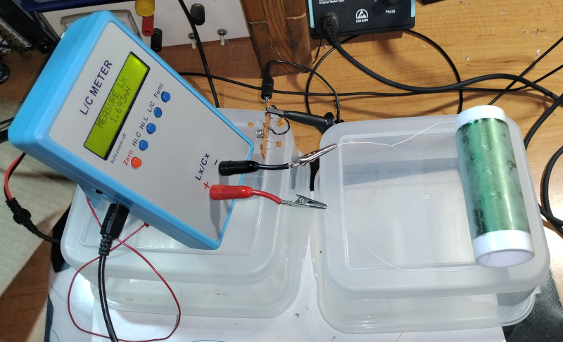
The other variant is a 1:1 type device, and is most often used in automotive audio and home stereo situations.  I recently measured the ground lift / isolation device provided with the Haken Continuumini:

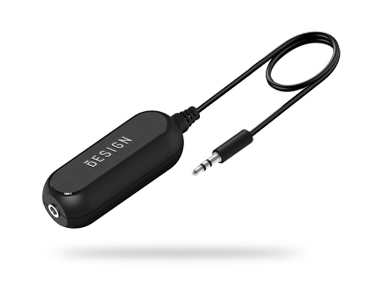
The windings on both sides have almost the same DC resistance, and driving a 1Vpp 1kHz sine wave into one side give a 1Vpp sine wave on the other.  So there is no impedance transformation going on, and no reduction in the output voltage, other than small magnetization losses.  However, there is quite a bit of bass distortion:

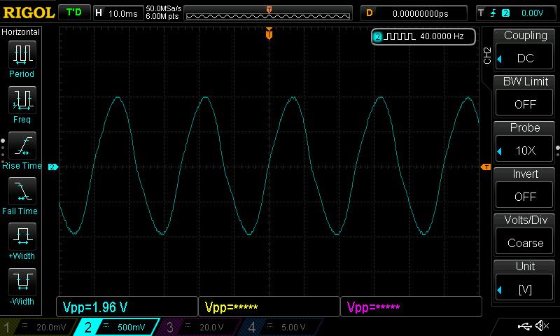
Above: An input of 1Vpp at 40Hz looks fine...

Above: 2Vpp at 40Hz has obvious distortion...

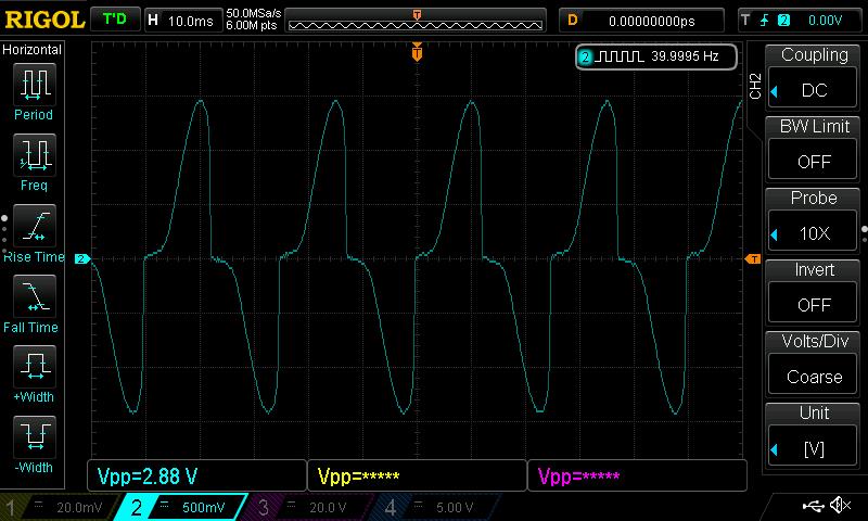
Above: 3Vpp at 40Hz is really bad, the tiny transformers inside are clearly saturating.  This confirms and somewhat quantifies my experience using it with the D-Lev a while ago.

I think all of these passive DI boxes are pretty much the same inside, only differing in the quality of the hardware (connectors, switches, box) and of course the transformers.  Some have attenuators to work with various input levels, which I assume are resistive and therefore lossy.

The active ones may add significant noise if not well designed.  And then you have the mixer phantom power / battery / wall wart to deal with.

The EW grounds through the AC plug, and I believe the Claravox does the same.  The Subscope probably grounds through the audio connection.  For the D-Lev, the DAC box gets the digital audio data optically via TOSLINK, so that is a ground isolation point if the DAC box is powered via a separate AC USB charger.  And there is always grounding via series 1nF to try too.

Posted: 5/14/2024 4:00:33 PM
André

From: 30 km south of Paris (France)

Joined: 12/23/2022

Dewster

The EW grounds through the AC plug, and I believe the Claravox does the same.

I have an EW standard and a Claravox.

"My" EW was supplied to me with two different unregulated AC power supplies :
- one for European sockets with a 2 pin connection (no ground connection).
- one for british sockets with a 3 pin connection but the ground pin is connected to nothing !

So, at least in Europe, the EW standard is not grounded through the AC plug.
I dont' know for the "EW plus" and the "new" Etherwave.

The Claravox power supply is a switching regulated 12 V DC supply.
The main connector is a 3 pin connector with ground.
The 12 V output connector is a coaxial plug. The ground sleeve of this connector is not connected to the ground pin of the mains connector.

For both EW and Claravox, I only ground my mixer and keep the instruments and amplifier isolated from ground to avoid ground loops.

My 2 cents of euro.


Posted: 5/14/2024 4:55:43 PM
dewster

From: Northern NJ, USA

Joined: 2/17/2012

André, could it be that some of the ground connections you tested maybe have small series capacitors, making them look like an open via DMM?

Posted: 5/14/2024 5:49:42 PM
André

From: 30 km south of Paris (France)

Joined: 12/23/2022

If this is the case, it is just inefficient as a grounding system.

When I received the EW with the two power supplies (one with fround, the other without), I asked Moog.
Firts, they said they were surprised that I found two supplies.
They also said that the ground pin of the british supply is not connected at all and that I need to ground the amp.

Posted: 5/14/2024 6:50:57 PM
dewster

From: Northern NJ, USA

Joined: 2/17/2012

"They also said that the ground pin of the british supply is not connected at all and that I need to ground the amp."  - André

Ah, very interesting André, thanks for that info!

Anyone in the US want to volunteer to check continuity between the Claravox DC barrel connection and the wall plug ground?

Posted: 5/14/2024 7:57:47 PM
André

From: 30 km south of Paris (France)

Joined: 12/23/2022

Sorry, I made a mistake (corrected in my message of 6:00 PM).
For the Claravox, the DC barrel and the wall plug ground ARE connected (checked with a DMM).
But I use a 2 wire cable and plug, in order to isolate the Claravox from ground and have a single ground connection on the mixer.

You must be logged in to post a reply. Please log in or register for a new account.