Let's Design and Build a (mostly) Digital Theremin!

Posted: 12/30/2016 9:12:24 PM
dewster

From: Northern NJ, USA

Joined: 2/17/2012

More progress.  Since the dither is being low pass filtered by the LC, I thought it might be interesting to try using the edges at the output of the LC as the event that snags the operating point and stuffs it into the 4th order LPF (I was using the output edge of the NCO to do this).  I also placed the 4th order software LPF at the end of all the other filtering (4x comb, 4th order HPF) to squash any truncation noise or "hash" coming from them.  What I ended up with is a 20dB, or factor of 10, reduction in the operating point noise:

I'm now seeing around 650 x 4 = 2600 or so peak to peak bobble, which is around 3 hex digits.  So I'm getting around 15 bits of clean difference between hand ~0.6m away and hand ~1" away from the pitch antenna, and I still haven't done much in the way of experimentation with noise shaping.  So far so good!  When you're doing numeric stuff you want all the numbers you can get.

Posted: 1/5/2017 9:13:27 PM
dewster

From: Northern NJ, USA

Joined: 2/17/2012

Spent several days trying out various noise shaping techniques, but nothing I've found lowers the noise floor.  Also found an evil SW bug (accumulator overlap in memory) that was causing the HPF "hash" and fixed that.  I'm having trouble even replicating the above, all of which has been somewhat discouraging.

So I'm looking again at digital offset heterodyning in Excel.  Not surprisingly, it is best behaved over a wide difference frequency band when two sines are multiplied.  It's simple to convert the NCO accumulator ramp to a triangle, and a bit of low pass filtering makes this fairly sinusoidal.  This works well for the local oscillator, but introduces quite a bit of amplitude variation when used for the variable LC oscillator.  And the LPF following the multiplier mixer introduces even more amplitude variation.  Though we are really only interested in the frequency of the result, not the amplitude.  Anyway, lots of filters, lots of trade-offs, and hard to know if it's worth it without actually trying it out in hardware.

Pawing over patents and papers on-line, it occurs to me that a sensor like this is really an FM receiver that goes all the way to DC.  We want a voltage (or number) that represents the static frequency deviation.

Posted: 1/6/2017 11:06:09 PM
dewster

From: Northern NJ, USA

Joined: 2/17/2012

Clarissa Dewster Explains It All - (DEIA)

I've had the feeling like something stupidly simple and unifying has been on the tip of my brain for a few days (months? years?) now, but not ready to float up through to consciousness.  This leads to much mulling at all hours, in hopes that I'm giving my subconscious enough technical fodder to work with.  On my scope I can clearly see a very steady signal out at 16.67ms trigger delay (to magnify phase change, and to kill mains hum), with enough resolution and SNR to play a song with my pinky movement alone at 1/2 meter or more.  It's got to be more than 16 bits of clean info. The digital oscillator seems fine, but how does one snag this digitally (for linearization and subsequent use by a digital voice synthesizer) without absolutely squashing the gestural bandwidth?  (Anyone can do it that way, and the trick is not to.)

This morning I realized that I've likely been going at things wrong by using the PLL frequency input to the NCO as the operating point output. Due to the PLL loop filter design, this number is only steady at NCO output edges, and has wideband intrinsic noise that impacts precision.  And after looking into down conversion via heterodyning some more, it seems like a big can of worms (at least digitally).  

My flash of insight was this: we want a fixed sampling interval (something like 48kHz so we don't hear changes or "zippering") and what we want to sample is the number of PLL output cycles - including portions of cycles - that have happened in that interval.  We want to sample the total phase change in the interval, and not the frequency per se.  Since the NCO is a phase accumulator, we can just give the accumulator more bits so that the roll over period is longer than the sampling period, then modulo subtract (differentiate) at each sample point to get the sample period phase change.  The difference in the extra NCO bits tells us how many integer cycles, and the difference in the NCO accumulator bits tells us the cycle fraction.

We are effectively building a CIC, or boxcar, filter in hardware and software.  The integrator is just the NCO with some extra bits in hardware, the differentiator or comb can be almost free in software, and the decimation (ratiometric lowering of sample frequency) is happening at the sampling point.  It is likely possible to do a higher order filter to lower the decimation alias noise, I'm currently reading Hogenauer's seminal paper from 1981 to see how internal CIC truncation works (oddly, no other paper I've encountered describes internal truncation).  Finally, I feel like maybe I'm getting a handle on a part of the design that's bedeviled me forever. It's been staring me in the face on my scope for years.

Posted: 1/7/2017 7:27:36 PM
dewster

From: Northern NJ, USA

Joined: 2/17/2012

DEIA (part 2) - How Is A Delayed Sweep Scope A CIC Filter?

When you look at a Theremin oscillator (good design, connected to antenna) on a scope with delayed sweep, you'll notice that some trigger delay values give you a very chaotic display, and others give you a very stable display.  The chaotic display is easy to understand: the strong mains electric field is coupling into the antenna and frequency (or equivalently phase) modulating the Theremin frequency, and this tends to decorrelate the delayed view of it, making it bobble around on the screen.  

The first stable delay point (if your AC mains supply is 60Hz) is found at the trigger delay of 16.67ms, which is simply 1/60Hz.  Why is the display stable here? This isn't too hard to figure out either: in the 16.67ms of memory the scope is storing exactly one wave of 60Hz disturbance, where the Theremin oscillator frequency increasing and decreasing over the same range, with the net result of zero.  So it doesn't matter where in the disturbance the scope triggers because it always holds one complete disturbance.  And this works for harmonics of 60Hz as well: two 120Hz 2nd harmonic waves will fit in 16.67ms of memory; three 180Hz 3rd harmonic waves will fit; etc.  

What does the frequency response of this delayed scope "filter" look like?

Like the above.  It's a rather severe filter in terms of limiting bandwidth, with lots of drooping around the harmonic comb zeros (60Hz, 120Hz, 180Hz, etc.) and increasing attenuation between harmonics (-13dB peak between the 2nd and 3rd; -18 peak between the 3rd and 4th; -21 peak between the 4th and 5th; etc.) and the -3dB point is around 27Hz.  Would a filter like this be OK for Theremin use?  Likely so, I believe it's near the edge of the lowest acceptable gestural bandwidth (though other Theremins currently exist with much lower bandwidth).  What's nice about it is a single filter kills all mains harmonics deader than vaudeville.

If we were going to implement a digital filter that functions like the above, what would it look like?  First off, it's clear (to me, from the mechanics and the frequency response) that it would function like a boxcar filter: we're averaging all of the samples over a certain period and adding them together.  When the next sample comes in we work the newest sample to the average and remove the oldest sample from the average.  So the number of samples in the average is fixed, and the samples are contiguous in time.  The average moves like a boxcar over the sample set, so it's also known as a moving average filter.  If you don't actually average but simply sum, the filter is more like a CIC, or cascade of integrators and combs (differentiators), and the output gain is obviously the number of samples in the sum.

(You might object and say "the delayed scope view isn't adding anything up!"  But (fortunately for us) we're not actually interested in the waveform details for our purposes.  All we want is the count of how many Theremin oscillator cycles there are in that 16.67ms of time.  And to achieve this the thing we sample is the NCO phase accumulator, because it can tell us exactly how much phase has happened since the last sample was taken.  But I'm probably getting ahead of myself.)

The naive approach shown at the upper left is to keep the samples in a shift register, and do the average with each new sample. This requires as many adds as there are samples, which seems wasteful.

A more sophisticated approach is shown at the upper right.  It maintains a running sum, adding each new sample to the sum, and subtracting the oldest sample.  This only requires two adds per new sample, regardless of how many samples are in the shift register.  The shift register and subtraction form a comb (a differentiator with more than one delay) and the running sum forms an integrator.

If you're really clever, you know that filter elements can often be moved about willy-nilly without affecting the transfer function.  At the lower right we've transposed the comb and integrator.  With some thought, and perhaps some simulation, it will be clear that the integrator can roll over all it wants to and the comb won't be bothered by this.  The stipulation for correct functioning is that the integrator roll over interval period be longer than the comb delay.  So you can feed a DC level into it without the internal numbers blowing up, and the output will be exactly what you get from the naive approach.  (The 1/n normalization in this last topology was omitted for clarity, you could just stick it on the end like in the second approach.)

Posted: 1/7/2017 9:54:38 PM
dewster

From: Northern NJ, USA

Joined: 2/17/2012

DEIA (part 3) - Quantifying Scope Observations

Looking at the 16.67ms delayed pitch side oscillator, I'm seeing ~25ns of phase noise.  16.67ms / 25ns = 666,800.  Moving my hand from my shoulder to maybe 2" from the plate antenna I'm seeing ~4% change in frequency.  So 666,800 * 0.04 = 26,672.  This is almost 15 bits of clean, stable information and should probably be OK for pitch computation use as-is.  It could likely be improved with a multi-order low pass filter placed somewhere between 100Hz and 1kHz.  

The trick is to digitally acquire this without significant degradation.

Posted: 1/9/2017 4:11:36 PM
dewster

From: Northern NJ, USA

Joined: 2/17/2012

Mains Filtering Via CIC

During my experimenting lately, listening to the audio version of the pitch operating point, and examining its noise levels and spectra via FFT,  I've noticed that the cascade of high Q comb filters (four of them) briefly lets mains hum through when I move my hand around in the pitch field.  It takes them a while to adapt to new DC levels, and while they are adapting they aren't doing a proper job of filtering.  They are probably better than nothing, but that's sort of debatable.

As we've seen above, a single CIC running at 48kHz with a delay of 800 samples (48kHz / 60Hz = 800) in the differentiator or comb section will let DC through, will aggressively smash all harmonics of the mains hum, and will provide high frequency roll-off.  So I coded up an unsigned CIC filter in Hive assembly, and replaced the cascade of high Q combs with this single filter.  Here is the HAL code:

/* CIC SUB - (0:in, 1:base, 2:depth | 0:out) */
lbl[0x50] s3 := mem[s1] // * CIC SUB START * get accum
          P0 += P3 // in + accum
          mem[s1] := s0 // store in + accum
          s4 := mem[s1+1] // get idx
          (s4 != 0) ? pc++ // modulo
          P4 := s2
          P4-- // dec idx
          mem[s1+1] := s4 // store idx
          P4 *= 2 // index * 2 for 32 bit access
          P1 += P4 // calc addr (pop idx)
          P2 := mem[s1+2] // get sample
          mem[P1+2] := s0 // store in + accum (pop addr)
          P0 -= P2 // in + accum - sample
          pc := P7 // * CIC SUB END * return

And here it is in action:

I removed the software 4th order LPF so you can clearly see the comb notches here at 60Hz, 120Hz, 180Hz, 240Hz, 300Hz, etc.  If you squint you can see attenuation factors described previously for the various lobe peaks in between the smashed harmonics.  Since the CIC has a gain equal to the comb delay 800, I shifted the filter binary input value to the right 10 places, which gives a total gain of 800 / 1024 = 0.78 or roughly 1.

I'm not hearing (or seeing) any hum or settling or anything else going on when I move my hand.  So unless I find a fatal flaw, or something better comes along, I'm sticking with this CIC as the mains hum filter.  In many ways it's just what the doctor ordered.

Theoretically, the CIC is an integrator followed by a comb section.  By itself the comb kills DC (has a gain of 0 @ 0Hz), by itself the integrator has infinite DC gain.  Quite conveniently, these gains cancel and give us a (normalized) gain of 1 at DC, while giving us zero gain at every mains harmonic, as well as the characteristic integrator low pass roll-off.

Posted: 1/14/2017 4:47:32 PM
dewster

From: Northern NJ, USA

Joined: 2/17/2012

"The trick is to digitally acquire this without significant degradation."  (-- moi)

Major milestone passed (like a kidney stone, LOL) yesterday.  I've been working on the LC DPLL SystemVerilog code, adding input parameters, auto calculating others (some that influence the hardware synthesis, others just for informational purposes), altering the clocking arrangement, and radically changing the way the pitch and volume operating points are obtained and processed.

I suppose parameters are a form of premature optimization, but when you have a filter-like structure such as a DPLL you don't want to have to stop and think for 10 minutes every time you change an accumulator width or a bit shift distance.  When you're experimenting it makes sense to implement the "knobs" you want to adjust as build parameters.  Otherwise, operator errors tend to get incorrectly chalked up as failed experiments.

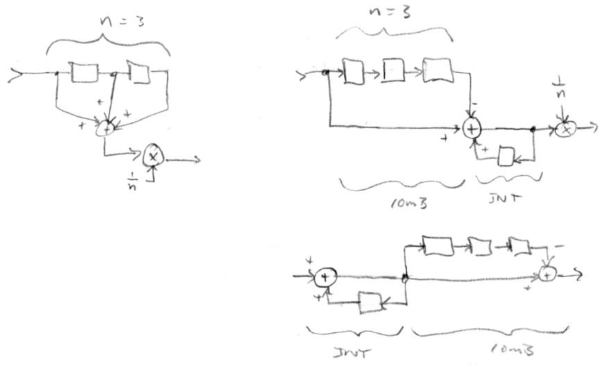
Anyway, the main breakthrough here is the implementation of a second order distributed CIC filter to get the pitch and volume numbers into the software domain of the processor.  There is an NCO in the DPLL, and if you think about it, what is going on is the accumulation of an input phase increment.  The larger the increment the higher the frequency of the NCO output.  What we want in software is a band limited version of the frequency increment, and I was doing this with a 4th order low pass filter in hardware.  What I'm doing now instead is to take the accumulator of the NCO and feed it to a second accumulator, and this combination forms a second order cascade of integrators.  The output of this is sampled at 48kHz and passed to the processor via an interrupt.  The software runs the sample through a second order cascade of differentiators - and voila! - out pops the NCO phase increment!  So the NCO is an integral part of a second order CIC, where half of the CIC is in software where it is exceedingly trivial and essentially free, and as a result I was able to remove a ton of FPGA logic.  (Hardware reduction isn't a high priority for this project, but it never hurts, because the more stuff you shovel into an FPGA the longer it takes to build, and the more difficult it becomes to meet timing closure.)

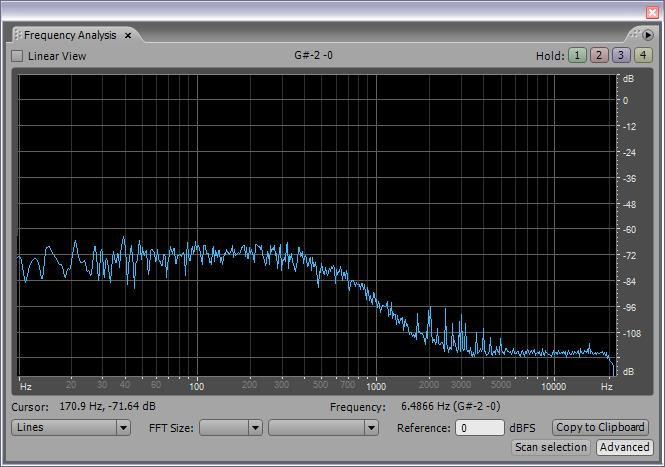
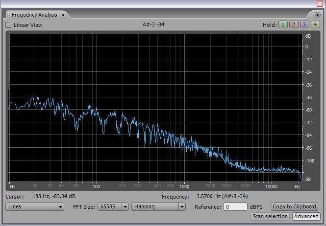
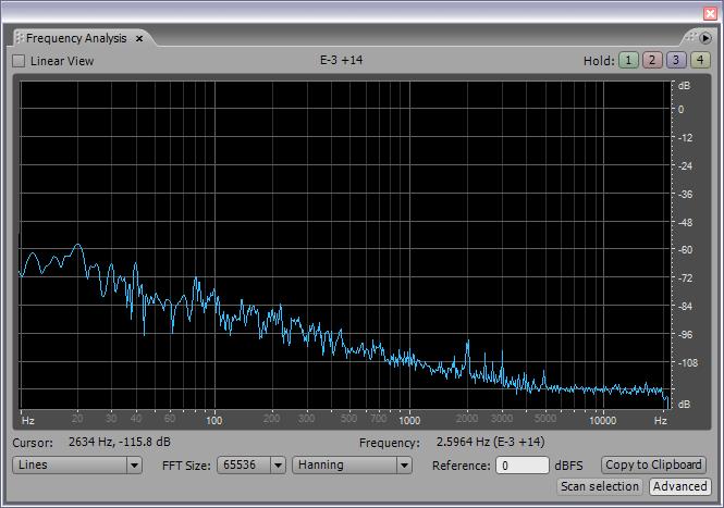
It was difficult getting all of this working, so I started with the first order CIC (just feeding the NCO accumulator - sampled at 48kHz - to the processor, and a single differentiating stage in software).  Once I got that running and felt comfortable with it, I tackled the second order case.  Here is what I'm now seeing in terms of spectra of the pitch operating point:

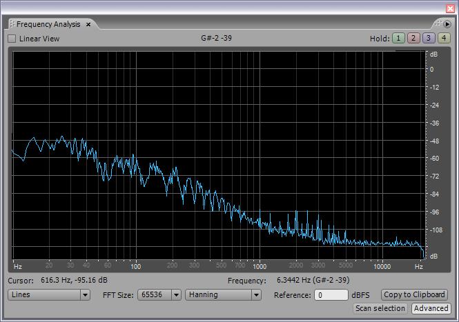
I'm doing a bit shift of 5 after the HW/SW CIC before feeding it to the mains hum CIC, then a 4th order LPF, and finally a 4th order HPF for the SPDIF output.  The software is also kicking the operating point out the UART connection, and I'm seeing six or more hex digits of really clean data there.

To get the HW/SW CIC decimation (down sampling from 180MHz to 48kHz) to work right I had to alter the clocking to keep the decimation factor constant.  So the DPLLs and the SPDIF would ideally both be clocked by 48kHz * 128 * 32 = 196.608MHz, but the closest I can get with an FPGA clock tree PLL is 50MHz * 59 / 15 = 196.667MHz, which is +298ppm off the exact number, but I believe this is OK for SPDIF.  It's about +1/2 a musical cent, which should be undetectable by human ears in terms of musical pitch deviation.  I had to work on the SPDIF component to get the speed up and to include a clock pre-scaler, but all of this has worked out rather well because the processor core clock is now largely independent of the Theremin logic clock.  Down the road I could perhaps get the processor core clock up to 197MHz, at at that point I could cascade the two PLLs and get much closer to the ideal SPDIF clock rate. 

Not seeing any sticky points, but there is a significant level of dither being applied to the LC tank.  The dither gets filtered by the LC, and this actually may be a problem, because the LC DPLL compares the input LC drive to the LC output and, since the input dither is quite a bit higher than the output dither, the difference is probably injecting large levels of noise into the downstream process.  I believe this large difference is also directionally incorrect in terms of phase error.  I will try independently dithering the reference and the tank (same noise but at different levels) to see if this helps to lower the operating point noise floor.  If it does, I may rewire the antenna drive boards to accommodate it (to keep the reference and quadrature analog delays the same).

This distributed HW/SW CIC filter integrated into the NCO is quite straightforward, economical, and very elegant - it's possibly one of my most fundamental contribution towards the realization of the modern digital Theremin, basically a stripped-down version of what's going on with the delayed sweep scope (though the scope scenario skirts aliasing by always triggering at the same point on the input wave).  It would be interesting to integrate the hum CIC filter into this too, but that would require excessively wide operations, and having the hum filter in software really isn't a big deal.  

Posted: 1/15/2017 11:23:18 PM
dewster

From: Northern NJ, USA

Joined: 2/17/2012

"I will try independently dithering the reference and the tank (same noise but at different levels) to see if this helps to lower the operating point noise floor.  If it does, I may rewire the antenna drive boards to accommodate it (to keep the reference and quadrature analog delays the same)."

Experimented with this today with inconclusive results.  Having the reference local to the FPGA and the LC tank output traveling over wires seems to inject a significant amount of environmental noise into the phase detection.  Seems as though it's time to break out the soldering iron and install a separate reference path through the antenna board.  Not a huge deal, and truth be told routing power through the CAT5 cabling has felt kinda faux pas'ish.

Posted: 1/18/2017 12:34:48 AM
dewster

From: Northern NJ, USA

Joined: 2/17/2012

Volume Side

After a couple of days of hard labor (generating, printing, stuffing, addressing, and posting 470 snail mails - volunteer work) I thought I'd try something easy like taking a gander at what the redesigned volume side is doing.  Using the same pitch side assembly code to examine it via SPDIF and UART, I only changed the attenuation (x2 less attenuation) before the hum filter to give it roughly the same full scale amplitude coming out of the UART (0x441CF086 is one number that just scrolled by in the terminal emulator):

This is clearly at least 12dB better than how the pitch side is performing, or roughly two bits of data SNR improvement.  I suppose it's due to the lower nominal operating frequency of the volume side.  Pitch side has a 330uH coil and runs around 2.5MHz.  Volume side has a 2mH coil and runs around 1MHz.  I was thinking the pitch side would have less noise due to being outside the AM band, but the minimum dither amplitude must always be around 1 logic clock, which means the pitch side gets perturbed more in a relative sense than the volume side, with the "more" here being ratiometric to the operating point (2.5MHz / 1MHz).  And dither gets injected and detected differentially, so it directly impacts SNR.

Hmm.  This makes me want to put the pitch side operating point below that of the volume side, and to use larger coils in general. Though the reason to put the volume side below pitch side is so that when the hand is really on the volume antenna and driving the frequency to ~1/2 nominal, it doesn't perturb the pitch side - so there's a design space tension here.  And I'm wondering how moot AM band interference with a high Q / high voltage swing tank is?  We're essentially receiving what we're transmitting, so it's all very local.

I should also mention that this isn't all apples/apples.  The volume PLL is running slower, and this makes the phase LPF cutoff that much lower than the pitch side (digital filter parameters track with sample frequency).  The proportionally lower dither and proportionally lower cutoff form a one-two punch, as it were.  The numbers at least makes sense from that angle.

Posted: 1/19/2017 10:39:11 PM
dewster

From: Northern NJ, USA

Joined: 2/17/2012

Seeing the better performance of the volume side was a bit surprising, though not so much in retrospect I suppose.  I'm working on a spreadsheet that may help predict a "sweet spot" for the operating point, though it's currently rather mired, or rather my brain is.

For the heck of it, today I cut down my largest air core inductor and stuck it in the rearranged pitch side plate antenna box:

I moved the driver board off the bottom of the box and located it on the side.  The inductor was also moved from the bottom corner of the box to the center of the plate antenna.  Using a new plastic cable clamp for the CAT5 wiring, so I was able to remove the blue masking tape there.  The inductor is ~100mm winding length of 34AWG single coat on 2" schedule 40 PVC, which gives ~9.1 mH with ~94 Ohms DCR.  The inductor had a center tap that I removed, and I trimmed the ends of the PVC to get it to fit in the box (though it bulges a bit).  I like this location of the inductor as the plate electrostatically shields it to some degree.  And since the "business" end of the inductor is oscillating at the same amplitude as the plate, it makes sense to stick them together.  As on the volume side, the coil is affixed via a friction fit plumbing knockout, which is bolted to the front of the box with a nylon screw, with the antenna plate sandwiched between.  Electrical connection between the coil and the plate (and the sense capacitor) is via a small coil spring on the left.

Results are interesting.  Resonance is around 450kHz, it requres 8x less attenuation in software to get the signal up, after that the SPDIF is similar SNR to the volume side.  I'm hearing faint aliasing tones in the SPDIF signal as my hand approaches and withdraws from the antenna, something I didn't encounter when running it at 2.35MHz.  Total Q seems about the same, with a 2.5Vp-p signal at the capacitive divider (which is 100:1, so the swing at the antenna is 250Vp-p).

Not sure where this is leading.  My (likely broken) initial spreadsheet predicts much higher Q of ~200 at this point, but I'm only seeing ~100.  The slightly audible aliasing probably isn't very relevant, but it's something to consider.  I really don't want to be winding huge honkering coils for ever Theremin I build, so I'm hoping the ideal (or near ideal) solution uses smaller ones than this.  And should the pitch operating point be above that of the volume, or vice versa?

You must be logged in to post a reply. Please log in or register for a new account.