


Haha, cat! Some time ago I was looking for dog vocal tract formants and, lo and behold, I found a paper about it which lists, alas only 2, formants vs. dog breed in a table.
I was not yet able to make notable use of that info, as I don't have a setup to produce the distorted, "violent" kind of vocalization dogs have, and I'm not sure I would put a huge amount of effort into it, but it would be funny ;-)
Let's Design and Build a (mostly) Digital Theremin!
Posted: 3/12/2018 11:14:56 PM
Posted: 3/14/2018 12:24:58 PM

"Some time ago I was looking for dog vocal tract formants and, lo and behold, I found a paper about it which lists, alas only 2, formants vs. dog breed in a table." - tinkeringdude
Ha! Animal formants aren't something I would have even thought of. I'm not sure how dogs do the barking thing, but a lot of audio stuff, when the process is sped up, takes on an entirely different character. So maybe it's something simple happening quickly?
Is this (link) the paper? This (link) chapter is good too, barks don't involve the nasal resonances as that is closed off.
=============
In a effort to modularize the code, I stuck a first order filter (low-pass, high-pass) together with a second order state variable filter (low-pass, band-pass, high-pass, notch) and made the first order operating modes negative values of a parameter, with zero a pass-through. Homing in on a single versatile filter "blob" that can do whatever I need it to do.
Digital filters tend to have more and more tuning error the closer you get to Nyquist (1/2 the sampling frequency) - the second order form goes a bit sharp, while the first order goes really sharp. Chamberlin gives formulas for correcting them, but in the end it comes down to polynomial approximation.
After dumbly staring at the chain of transformations I had in front of the second order frequency for too long I decided to trash it and go with a single polynomial that does it all, which simplifies and speeds things up. A simple polynomial that gives almost 16 bit precision is 0.547946x - 0.0271x^3 and this takes care of the maximum frequency being C9 (8372Hz) for full-scale input as well.
For the first order filter I found the polynomial x - (x^3)/3 to give 8% or so error max (and on the low end), which sounds like a lot but there is no peaking or resonance that might reveal the exact frequency it's set to, so tuning isn't nearly as critical. We mainly just want to tame the super sharp high end, and ideally the max error would be located there, but even if you wanted to get surgically precise, the high-pass cutoff diverges from the low pass cutoff at higher frequencies, and the high pass response oddly gains up somewhat as well. They have their uses, but first order filters are mushy sorts of affairs, and it doesn't pay to go too crazy on them.
For just about anything that really matters in music synthesis (pitch, waveform fidelity, noise floor, etc.) I've found 16 bit precision to be a reasonable, rough-and-ready target.
Posted: 3/15/2018 1:40:44 PM
Footloose
Made a new parameter type that gives 64 1.5dB steps and tried using that for mixing and volume levels. But it turns out I prefer the simple parameter squared response, as it provides an expanded 0 to -30dB or so over this most used range, with a smooth transitioning drop to zero (a denorm for logs). In particular I wanted dB for the formants, to make the preset settings more scientific, but oh well. Who'd think something as simple seeming as volume control could be so complicated? The digital world lacks the (literally) canned solutions to these kinds of things that the analog world has enjoyed since the beginning of time.
But the 1.5dB step parameter type does work quite well for filter damping. There's a minor debating society in my head on using Q (Q = 1/damping) instead, as dialing up the Q makes the filter more resonant. But the default state of the filter is infinite resonance, which is reduced via damping. And damping goes from [0:1] (I've excluded critical damping of 1.414 as it can make the filter unstable at high frequencies) whereas Q goes from 1 to infinity, so damping is easier to implement as a preset parameter in the code and on the screen. (But if this were analog I'd go with a Q knob instead.)
This new precise control over the low end of damping has revealed an issue with the resonance that I was hearing sometimes: unnaturally fast decay at lower amplitudes when the filter is set to ring like a bell. It's particularly obvious when several filters are set to different frequencies and "struck" together. The higher frequency filter will reach some point in the decay first and drop like a rock in a linear, rather than exponential, manner. The lower frequency filter will do so too, but will take longer to hit the linear point, and the contrast between them makes it really stick out.
I thought the modified Chamberlin, with the frequency fractional multiplications positioned after the integrators, was immune to this sort of behavior, but apparently not. The behavior is clearly a resolution issue, where the decaying values in the filter loop hit some point where they don't behave sufficiently continuously (i.e. when small numbers are attenuated and used for subtraction).
Taking a step back, the filter frequency setting is actually attenuation, and attenuation in a feedback loop translates into gain (feedback flips everything on its head) so the integrator headroom (the room the accumulated value has to expand before hitting the 32 bit register width limit and rolling over) decreases with decreasing frequency setting. I've got things set up now so ~32Hz is the lowest setting, with ~8kHz the top, which gives 8 octaves, which is 8 bits of dynamic range. Gain in the loop is also directly set by the damping, with lower damping giving higher gain and lower headroom. You can never really control these things enough to avoid clipping/rollover somewhere, but if we have a 16 bit audio value and 32 bit registers, we have 16 bits of headroom, 8 of which are consumed by the frequency attenuation. If we reduce the input amplitude in order to accommodate the resonance (no point in getting more than 16 bits at the output) we have 8 bits of headroom left.
So I took this headroom and turned it into "footroom", or room at the bottom, by shifting the filter input up 8 bits and shifting the output down 8 bits (signed shift here). And this seems to have cured the annoying decay issue completely.
Analog or digital, seems there's lots of tinkering to do at the end, though the nature of it is quite different. It's unavoidable, many times I've seen my own stuff go from lame-ass crud to fairly acceptable after a diligent application of elbow grease. The trick, it seems, is in knowing when to stop tinkering.
Posted: 3/15/2018 9:25:17 PM
Very interesting paper on violin formants and how they relate to human formants: "Stradivari violins exhibit formant frequencies resembling vowels produced by females" by Hwan-Ching Tai and Dai-Ting Chung (link). Nice tables of various violin and human formants.

Posted: 3/18/2018 5:54:26 PM
... you and other theremin builders/effect manufacturers try emulating the human voice by electronics, but Stradivari did it by wooden hardware... - ILYA
Yes, the confluence of aesthetics & physics underlying Clara's Theremin voice, the human voice, and the violin is blowing my mind a bit.
===========
Doing some reading today regarding turbulent noise and random variation in vocalization. Here is a nice paper where they use a guitar talk box and white noise to characterize the vocal tract ("Using a White Noise Source To Characterize a Glottal Source Waveform for Implementation in a Speech Synthesis System" by Brandon R. Graham):
https://digitalcommons.usu.edu/cgi/viewcontent.cgi?/&httpsredir=1&article=1246&context=gradreports
What I found most interesting was the discussion of jitter / shimmer for the glottal source. They characterized the bandwidth of both, as well as the correlation between them, and came up with an economical 2nd order combo filter + delay. I need to give this a try, anything that might improve the realism would be super welcome.
Posted: 3/18/2018 6:45:31 PM
Simple Baffle Simulator
Speaker baffles don't get too much simpler than the square ("diamond") shape that Theremin came up with. To simulate it from the perspective of a listener positioned directly in front of it, due to the open back the back wave comes around and mixes with the front wave. The back wave is 180 out of phase, so it is destructive, though it has to travel farther than the front wave, and this distance depends on how it finds its way to the front. The speaker isn't a point source either, but is on the same scale as the baffle, which further "smears" the back wave timing.
If we imagine the square dimension is somewhere around 2', we know sound travels at roughly 1' / ms. With a 48kHz sampling frequency a 1ms delay takes 48 samples. So the general back wave delay is around 96 samples. The square gives us a travel distance variation of 0 to 0.8 (from 2 * (1 - 1.414)) or 40 samples with an output tap for each. Due to the geometry these are roughly equally weighted, so we can use a boxcar or CIC filter to implement it economically. The CIC has a gain directly proportional to the sample delay, so that has to be figured in as well. We destructively add this to the direct signal (i.e. the front wave) and the low pass filter at the end is for modelling the high frequency roll-off of the speaker itself, which should be around 4th order with a cutoff around 4kHz (though I haven't implemented this yet):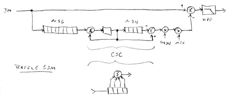
Playing around with the parameters, I found a common delay of around 60 to 80 to sound the most realistic, with lower values giving more pronounced midrange, and higher values edging on audible delay type stuff going on. I also found the CIC delay of 24 or so to give decent blurring of the upper end of the comb filter type sound. Since these delays are adjustable, the CIC gain compensation is via LOG2, NOT, EXP2 which gives an exponent of -1, or inverse. The mix knob allows control over the back wave signal from 0 to 2, and settings from 0.25 to 2 work well.
It's not super magical sounding, though it does impart some complexity to the sound that wasn't there in the first place. Integrating room reverb into the whole thing would almost certainly help, but I don't have the memory to spare.
[EDIT] A quick sample (link) of the baffle sim, first is full mix, second is half mix, third is none. The following is a passage 2x with violin formants performed an octave apart, the lower is violin-like, the upper female vocal-like. The last is a wah-wah vocal / sad trombone. Everything has about 1/3 mix baffle sim.
Posted: 3/18/2018 7:26:14 PM
Volume & Pitch Axis Modulation => Filter
This was a surprisingly difficult issue for my lame brain to grasp and finally puzzle through. I wanted it to have as few knobs as possible, but with as much flexibility as possible. Here is what I finally settled on:
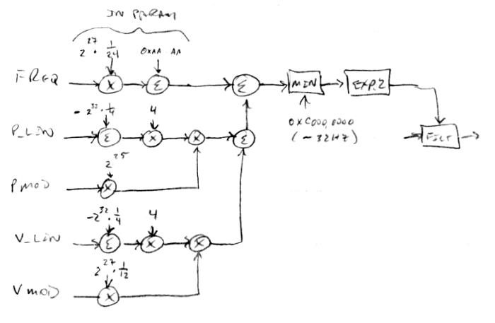
Keep in mind that the internal linear pitch and volume axis representations are unsigned 5.27 values. At the bottom, the +/-Vmod knob value is gained up to give one note per detent. The unsigned linear volume number from the volume axis has 3/4 (full scale) subtracted from it, with the result gained back up to full scale, and these are combined via multiplication to yield a signed value. Similarly, the +/- Pmod knob is gained up and combined with the subtracted and scaled linearized pitch axis number. These are combined, and also combined with the unsigned FREQ knob value (which is 5.27 scaled via the parameter system). The result is minimum limited to ~32Hz, exponentiated, and fed to the filter frequency input. The minimum frequency limit minimizes static and popping that otherwise happens when the filter is set to too low a frequency and then quickly increased.
It works as you might think, zeroing out Vmod and Pmod gives sole center frequency control to FREQ, which has 1/2 note resolution from ~32Hz to ~8kHz. Positive and negative settings of Vmod give positive and negative influence over center frequency based on the volume hand position. And positive and negative settings of Pmod give positive and negative influence over center frequency based on the pitch hand position. You have to play around with it a bit more than I would like, e.g. increase FREQ when dialing Vmod or Pmod negatively, but it does what I wanted it to do. Setting Pmod to 30 gives a tracking filter (with offset FREQ) so you can simulate fixed waveforms that way.
The thing that got me the most was in deciding how to handle zero axis values, and I did this by limiting the dynamic range via subtraction and scaling. On the volume side this threshold is -48dB of full scale (~edge of audibility) and on the pitch side this threshold is ~32Hz (again, ~edge of audibility). These both work out to 8 bits of dynamic range (not to be confused with resolution here, which is much higher). It's pretty weird that volume and pitch, and the ranges of both, scale so similarly for the human ear, and that they are both perceived as LOG2.
[EDIT] An MP3 sample (link) of the envelope generator with some filter frequency volume (negative) modulation. First half is odd harmonics, second is all. The overloading here is intentional for effect, and I believe it's happening at the filter.
[EDIT2] And here (link) is a sample showing the nice decays of the filters now that they have adequate "footroom".
Posted: 3/20/2018 2:15:58 PM
Jitter & Shimmer
I tried adding 2nd order low pass filtered noise to the pitch (jitter) and volume (shimmer) - this seems like a dead-end for vocal synthesis via a Theremin controller. In retrospect, Theremins already have enough (some would say too much) variation in these parameters during normal playing, so this is a situation where more is less. Though I can see the need for them if you're using software or a keyboard or some other rigidly discreet one dimensional control to do vocal synthesis. If carefully adjusted, jitter in particular can add realism to highly static pitch (I jacked up the pitch correction to quantize in order to test this).
In many ways a Theremin controller is highly suited for simple (singing vowel) vocal synthesis. Though it (or I should say the player) isn't very good at staccato volume and rapidly changing discreet pitch, something that the human voice can do fairly easily.
I sort of question the paper I pointed to a few posts back regarding this issue. They show a cross correlation delay of ~1/4 second between jitter and shimmer, and I suspect this may be due to the ways they're processing and extracting this data, rather than any real delay. Off the top of my head I can't imagine any physical process in the human vocal tract that would produce highly correlated pitch and volume variation with that large of a delay between them (though filters set to really low cutoff frequencies can easily introduce large phase delays).
Posted: 3/21/2018 3:36:00 PM
Vocal / Breathy Transition
I can get very realistic breathing sounds using band pass filtered noise as the glottal source. And my phase modulated sine glottal wave gives fairly realistic vowels and fry sounds. But how does one synthesize transition sounds? Simply adding the sources is sorta close but doesn't really cut it, and the onset of periodicity sounds somewhat non-periodic. Something decidedly non-linear is going on here.
Reading papers on synthesizing breathy voice, I found one that added 2kHz high pass filtered noise, gated at the glottal rate, with fixed phase offset and duty cycle. The phase is important, I found 0 and 360 degrees to impart a weird DSP-ish burbly sound, with 180 degrees the sweet spot. And, as the paper says, 50% duty cycle is about right. I experimented with the high pass cutoff and Q, and also with the use of triangular gating rather than rectangular (on/off). But it doesn't sound realistically breathy to me. Fry sounds are strange as you can hear the noise gating, and for higher glottal frequencies (F0 in the parlance) it just sounds like additive noise. A dead end I think, at least for this project.
Grabbing the bull by the horns, I whipped out a small microphone and the nearest handy larynx (my own). Jacking my jaw and lips wide open and sticking out my tongue seems to minimize many of the confounding resonances. And placing the microphone inside my mouth reduces much of the confounding nasal resonance (and throat) radiation. Strong resonances remain, but certain details are clear-sh. Here it's going from rough fry to vocal:
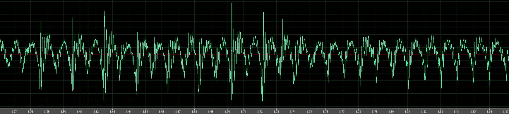
1. Much of the randomness seems to be a random amplitude spike at the beginning of the glottal wave.
2. At some levels of vocal effort, this spike seems to favor every other glottal wave, producing a sub-harmonic you can see in the FFT view.
3. The vocalization glottal wave itself looks very much like a rectified sine wave, with some tilt, just like in the papers.
So the vocalization transition doesn't seem to be as simple as "add some noise to this or that" but "add a periodic randomized amplitude spike of some sort in a statistical manner that favors the first sub-harmonic".
You must be logged in to post a reply. Please log in or register for a new account.