Let's Design and Build a (mostly) Digital Theremin!

Posted: 11/12/2024 10:30:14 PM
dewster

From: Northern NJ, USA

Joined: 2/17/2012

3D Printing Coil Forms

I didn't have plumbing handy for sarob's coils, and while it's not a big deal to run down to the Home Despot and grab some, I thought this might be a good opportunity to instead do a bit of experimentation.  So I whipped up a simple 38mm diameter cylinder in OpenSCAD, sliced it with 4 outer walls, no end walls, and no fill in Prusa slicer, and printed one 99mm tall and another 109mm tall.  

Winding the 99mm with 30AWG was a little tricky, I had to keep pushing the windings together to make them tight.  I realized what was fighting me here was the printing grooves associated with the printing layer height of 0.25mm vs the 30AWG single coat diameter of 0.28mm.  Anyway, that coil measured a tad over the target 1mH, which was fine. 

Winding the 109mm with 32AWG went considerably smoother, but at the end it measured 1.62mH instead of the expected 2mH - what's going on?  The OD of 32AWG single coat is 0.22mm, but that measured fine.  Taking a jeweler's loupe to the coil revealed tiny spaces between the turns - the wire was riding the printed layer grooves like a phonograph needle!

So I printed two more forms, the 99mm with 0.28mm layers, the 109mm with 0.22mm layers, and this time both coils wound pretty easy and measured correctly.  I spray satin varnished them, and when that was dry I applied the heat shrink tubing.  I was a little worried that the PETG, being a thermoplastic and all, might deform during the heating of the heatshrink, but it went fine.  I think the nail polish and varnish doping stick better to PETG than to ABS / PVC.

Above, left to right: (good) 1mH w/ 0.28mm layers, 2mH w/0.22mm layers; (ok) 1mH w/ 0.25mm layers; (bad) 1.62mH w/ 0.25mm layers (which I didn't bother to heatshrink).

The forms take on the order of 2 hours to print.  If I had a faster printer I'd probably go for a double wall with cubic fill, just to make things more rigid.  PLA would be more rigid than PETG and can be printed faster, so maybe I'll give that a go next time.  Printing is pretty inexpensive, each form is like 75 cents of plastic; plumbing costs somewhat more though it's not prohibitive, and it certainly is convenient to buy something more or less ready-made.  The printed layer grooves are a nice guide to get things going with the wind, but they fight you somewhat during the wind, so it's a bit of a mixed bag.  I've found that printing just about everything for the kit has been the best way to go: highly custom parts with no reliance on anything except the raw material.

Posted: 11/21/2024 3:57:02 PM
dewster

From: Northern NJ, USA

Joined: 2/17/2012

Wrap It Up

High Q coils apparently require a certain distance between adjacent windings.  Scramble / basket winding can do that because it spaces out the windings, makes them somewhat non-parallel, and introduces gaps.  Wire insulation / varnish / coil dope has a higher dielectric constant than air / vacuum, but from our simple testing it maybe doesn't seem to be a huge issue?  So instead of a complex & difficult winding process, could we instead use wire with a thicker insulation?  If so, where might we buy super heavy build copper wire?

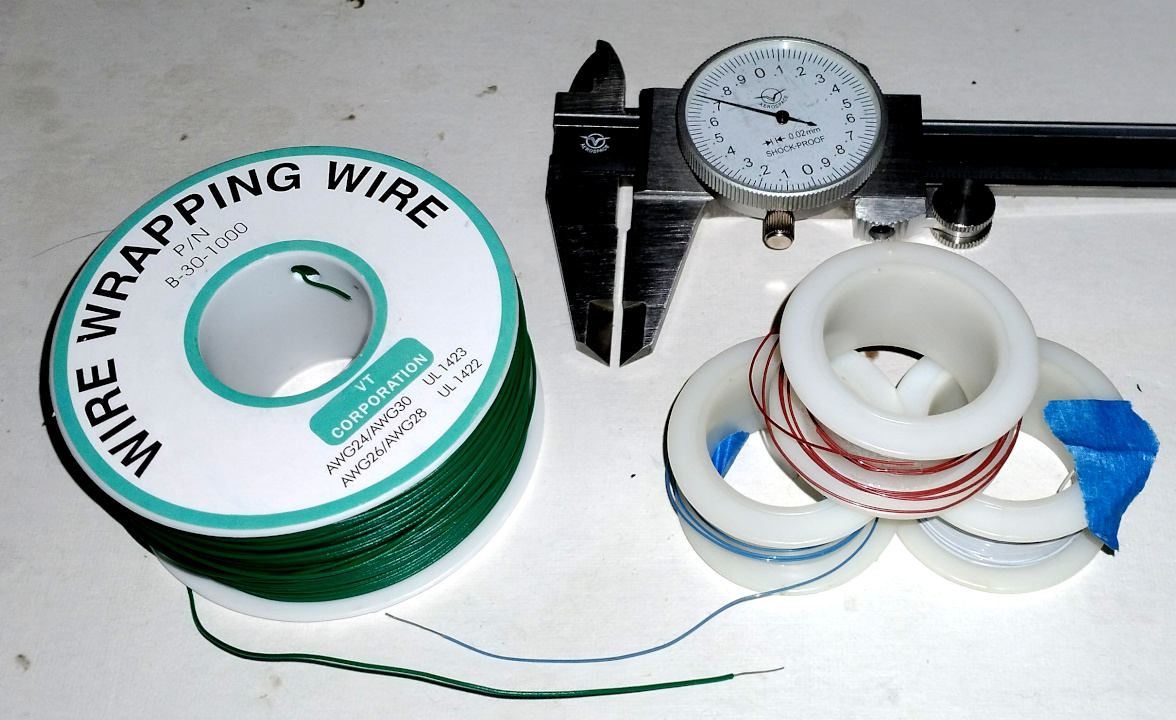
Wire wrap wire is one possibility:

Above: On the left is a spool I bought off Amazon recently, the copper wire inside measures 0.22mm in diameter (~AWG 31), the insulation 0.68mm in diameter, which I believe is PVC because it feels kinda soft, and I wouldn't recommend this wire.  On the right are some old spools I bought long ago at Radio Shack (RIP) with 0.26mm (AWG 30) wire / 0.45mm insulation, which I believe is Kynar, a trade name and a specific formulation of PVDF [LINK].

Kynar, being a harder insulation, would probably make for a more physically stable wind, and the somewhat thicker CU would give lower DCR and hopefully higher Q.  I see spools of 1000 feet (300m) of what they claim to be Kynar 30AWG selling for $40USD on eBay.  A 20mH coil would consume most of it, making for a rather expensive wind!

Posted: 11/29/2024 5:24:39 PM
Buggins

From: Porto, Portugal

Joined: 3/16/2017

Current sensing AFE for D-Lev

LTSpice model is available on github

Advantages

* Current sensing approach - less noise (sensing point is isolated from antenna by inductor)
* Sine drive waveform probably can reduce noise (3rd sallen-key LP filter used to convert square drive signal to sine wave)
* Can drive high Q inductors
* Although current through LC tank at resonance is in-phase with drive signal, this schematic provides 90 degrees D-Lev compatible phase shift at resonance.


Interface

* Drive input: square 3.3V signal from FPGA
* Feedback output: squared copy of a drive signal passed to antenna, shifted by 90 degrees for D-Lev DPLL compatibility.
* Sense output: squared copy of current sense signal.
* Power supply: +5V, two linear regulators - for 4.5V and 3.3V
* Ground


Square 3.3Vpp input is converted to (almost) pure sine drive with LP filter.

Inductor current and antenna voltage swing (for 2mH 120 Ohm series resistance inductor, 2.4Vpp sine drive)

Outputs compatible with D-Lev: near resonance, phase shift is 90 degrees.


Higher Q inductor probably will let to have above 1KV Vpp

BJTs may be replaced with ICs.

LP filter buffer can be built using almost any fast enough opamp.

The rest of BJTs - Current Feedback Operational Amplifier. CFB OpAmp IC should have low power supply voltage.

Candidates:

* LT6210 - can work from 3V, up to 80mA drive current, EUR3.91 on Mouser, not in stock on JLCPCB (estimated price $2.16)
* LT6211 - dual, can work from 3V, up to 75mA drive current, EUR 3.99 on Mouser, not in stock on JLCPCB
* LMH6723 - can work from 4.5V EUR2.5 on Mouser, not in stock on JLCPCB
* LT1395 - min supply voltage 4V, up to 80mA drive current, Mouser price $3.38, not in stock on JLCPCB (estimated price $1.7)
* AD8014 - min supply 4.5V, drives 40-50mA load, EUR 4.54 on Mouser, in stock $2.99 on JLCPCB
* AD8000 - min supply 4.5V, drives 100mA, $5.7 on JLCPCB
* OPA2675 - dual, min supply 4.5V, can drive 1000mA!!! mouser price EUR3.28, in stock on JLCPCB $4.47


Posted: 12/1/2024 9:32:39 PM
dewster

From: Northern NJ, USA

Joined: 2/17/2012

"Current sensing AFE for D-Lev" - Buggins

Very clever Vadim!  

I've been playing with it here and there (hence my delay in responding to you) and I can follow it up to DRV_SINE: LPF with double follower drive and filter feedback, biased by constant current sources.  After that another current source biased set of followers with offsets to drive a dual current mirror and output stage.  I get a little lost around C9 and what's going on with Q97 and Q104?  R30 seems to need to be a low value to give the 90 degree difference between drive and sense?

Converting the square drive to sine via LPF is probably a good move as it eliminates switching edge noise, though it lowers the voltage swing due to the fundamental amplitude limit being only as large as the supply (a square wave has a small advantage here as the fundamental Vpp is greater than VCC).  I get a little nervous when a lot of gain is required in order to jack up tiny voltage swings, like those across R30 and R59, though that's sorta going on in the current AFE when the DPLL isn't locked.

I don't like having to "tune" the C divider in the current AFE, and it would be nice to sense things on the other side of the inductor, though the sine is pretty pure at the antenna and the phase is naturally a quadrature at resonance.  Some sort of clipping circuit would be better than a divider, but everything I've been able to come up with introduces an unwanted phase shift.

Posted: 12/2/2024 9:01:36 AM
Zhuoran

Joined: 11/29/2024

Wrap It UpHigh Q coils apparently require a certain distance between adjacent windings.  Scramble / basket winding can do that because it spaces out the windings, makes them somewhat non-parallel, and introduces gaps.  Wire insulation / varnish / coil dope has a higher dielectric constant than air / vacuum, but from our simple testing it maybe doesn't seem to be a huge issue?  So instead of a complex & difficult winding process, could we instead use wire with a thicker insulation?  If so, where might we buy super heavy build copper wire?Wire wrap wire is one possibility:Above: On the left is a spool I bought off Amazon recently, the copper wire inside measures 0.22mm in diameter (~AWG 31), the insulation 0.68mm in diameter, which I believe is PVC because it feels kinda soft, and I wouldn't recommend this wire.  On the right are some old spools I bought long ago at Radio Shack (RIP) with 0.26mm (AWG 30) wire / 0.45mm insulation, which I believe is Kynar, a trade name and a specific formulation of PVDF [LINK].Kynar, being a harder insulation, would probably make for a more physically stable wind, and the somewhat thicker CU would give lower DCR and hopefully higher Q.  I see spools of 1000 feet (300m) of what they claim to be Kynar 30AWG selling for $40USD on eBay.  A 20mH coil would consume most of it, making for a rather expensive wind!

Another possible method I can think of is to wind the coil using two (or more) wires in parallel. One makes up the coil, and the other spaces the windings out. The second wire can be made of any material. It can be removed after the winding is finished, or left there if it's not magnetic or conductive. This is probably more difficult than using a single wire, but should still be easier than basket/honeycomb winding. One potential problem is that the friction between the wire and the former is normally quite low, if we remove the second wire, there will be space for the first wire to slide. We may need to use some adhesive to stick it to the former (which also has a higher dielectric constant than air / vacuum, though).

Posted: 12/2/2024 10:59:57 AM
Buggins

From: Porto, Portugal

Joined: 3/16/2017


I've been playing with it here and there (hence my delay in responding to you) and I can follow it up to DRV_SINE:
LPF with double follower drive and filter feedback, biased by constant current sources. 

After that another current source biased set of followers with offsets to drive a dual current mirror and output stage. 
I get a little lost around C9 and what's going on with Q97 and Q104? 
R30 seems to need to be a low value to give the 90 degree difference between drive and sense?

Everything to the right of DRV_SINE point is just a current feedback opamp on discrete BJTs (WikiIC Op-Amps Through the Ages).

C9 is needed to prevent positive feedback in the loop. Try removing it or reducing to 1-2pF on the model, and see feedback current waveform.
10pF - 100pF should work fine. Some of current feedback opamp ICs expose this point to allow connection of external cap.
Bigger C9 reduce bandwidth of the amplifier a bit, and increase feedback current.

Q97/Q104 current sources may even work driven with constant current, but using the same current as in current feedback part, as I understand, gives flexible power consumption.
On lower load, low current for driving output emitter followers will be used, but under higher load, this current will be increased automatically.
Actually, everything after C9 is just a 1:1 buffer.

R30 may be even 0 if you don't need to use it as a sensing resistor. But sometimes even IC CFB opamps have this resistor in current feedback in recommended designs.
Alternative way to sense the same current is to add one more copy of the current with current mirror.
90 degrees phase shift in feedback current is a kind of surprise for me.
Of course, some other method to get a 90 degrees shift can be used - e.g. passing of drive signal through integrator.

Current feedback opamp ICs often use advanced 4-BJT current mirrors which reduce available voltage swing by additional 2*0.7V.
Therefore unless we are going to use some step-up converter to get bigger supply voltage, we need to choose IC which support lower supply voltage (assuming they have simple current mirrors).

Converting the square drive to sine via LPF is probably a good move as it eliminates switching edge noise,
though it lowers the voltage swing due to the fundamental amplitude limit being only as large as the supply (a square wave has a small advantage here as the fundamental Vpp is greater than VCC).

Current feedback opamp anyway has a limitation on output swing due to its emitter follower output cascade, 0.9..1.0V from the rails.
So, shifting of 3.3V square signal up to align at the middle of 4.5V supply, followed by LP filter which reduces the swing is actually good, because 3.3V swing for 4.5 supply exceeds limitations 4.5-1-1=2.5V
Actually, if LP filter output has too low swing, you may introduce the gain, by adding of resistive divider from opamp output to ground and feed negative opamp input from there.
But if gain 1 in LP filter is enough, you can get rid of LP buffer at all, by reusing output buffer as buffer for sallen-key LP filter (model is available in _v02.asc file on github).


I get a little nervous when a lot of gain is required in order to jack up tiny voltage swings, like those across R30 and R59, though that's sorta going on in the current AFE when the DPLL isn't locked.

I don't like having to "tune" the C divider in the current AFE, and it would be nice to sense things on the other side of the inductor, though the sine is pretty pure at the antenna and the phase is naturally a quadrature at resonance.  Some sort of clipping circuit would be better than a divider, but everything I've been able to come up with introduces an unwanted phase shift.


Feedback current does not depend a lot on drive current - e.g. drive 35mA has 1.1mA feedback current, 7mA - 0.8mA. So R30 does not need to be tuned.

But for R59, probably some tuning is still required - e.g. choosing lower value for high-Q coil and higher value for a normal coil.
The bigger R59 is, the more drive voltage swing is lost on it.
The lower R59 is, the less swing is lost, but the more problems it may cause when drive frequency is far from resonance.
Probably, it's something to be improved. Adding of diff amplifier cascade before comparator may help.

Posted: 12/2/2024 2:05:55 PM
Zhuoran

Joined: 11/29/2024

Buggins, here's my understanding of your first circuit. Am I correct?
Q223-228 form an unit-gain buffer. Together with R176, R177, R180, C25-27 they form the Sallen-Key LP filter (as shown on the schematic).
Q82, and Q88-104 forms the current-feedback operational amplifier (as shown on the schematic).
Q82, Q88, Q95, Q96 forms a current source for the input stage of the CFOA, together with Q89 and Q90, they provide bias for Q91 and Q92. Voltage at the base of Q91 and Q92 is always 2 diode drops apart.
The junction between the base of Q89 and Q90 is the non-inverting input (IN+), the junction between the emitter of Q91 and Q92 is the inverting input (IN-), and the junction between the emitter of Q101 and Q102 is the output.
Q93, Q94, Q98, Q103, and C9 forms the I-to-V converter, Q97, Q99-102, and Q104 forms the output buffer.
IN+ has relatively high impedance, IN- has relatively low impedance.
IN- follows IN+, thus the current through R30 is caused by the voltage difference between the output and IN+.
The amplifier is configured in a way such that the output follows IN+, with (approximately) unit gain.

You must be logged in to post a reply. Please log in or register for a new account.