Let's Design and Build a (mostly) Digital Theremin!

Posted: 3/1/2014 11:51:02 PM
FredM

From: Eastleigh, Hampshire, U.K. ................................... Fred Mundell. ................................... Electronics Engineer. (Primarily Analogue) .. CV Synths 1974-1980 .. Theremin developer 2007 to present .. soon to be Developing / Trading as WaveCrafter.com . ...................................

Joined: 12/7/2007

"Fred, what do you think of my interference conjecture up-thread?" - Dewster

I think its a damn good hypothesis.

I did a lot of playing about with volume-control type circuits, to use for driving voltage controlled synthesis, and the simple (diode / rectifier) schemes never worked well, and were subject far more to interference than other schemes..

I never really connected the dots - I simply moved on to other topologies (like monitoring the drive current)

Im not a great fan of AM detection anyway, so never persued this route - when I saw problems, I simply dumped it.. I try not to do that, try to look at the causes of problems to increase my understanding, but theres only so much time... Some stuff I enjoy working on, so spend more time on these - AM and radio stuff in general hasnt excited me since the early 70's when I bought a dysfunctional ex army  valve communication reciever, and got it to work so I could listen in to police / security channels ;-)

What you say makes a great deal of sense to me!

One minor counter argument could perhaps relate to the orientation of the volume antenna ? my experiments were all with vertical rod antennas as I was focussing on pitch - I think that pitch antennas could interfere with volume antennas on other theremins, but there would be a big decrease in volume <-> volume antenna interference due to their horizontal orientation (bulk capacitance being on the Y axis) (geometry)

in terms of EM interference, I dont know... But volume loops are probably just as suseptable as rods, I would guess....

Fred.

Posted: 3/2/2014 9:32:19 AM
livio

Joined: 2/2/2014

Dewster, Thank you to have hosted my really bulky posts. I did not realize that this could weigh down a thread. If you want I can delete many of them, when they do not talk about technical things (such as this). I could also reduce the others to a few lines by removing many bulky images. 

I'm trying to learn how to make a thread, but I'm already stuck with the name. Do you have any idea? I do not want to give the impression to advertise our system. How could I call it? Maybe it's better that I do not create a thread?

My messages were just tips to help you in your FPGA. Apart from that, I do not know what to write, all you need is already available on our website.

Posted: 3/2/2014 1:33:05 PM
dewster

From: Northern NJ, USA

Joined: 2/17/2012

livio, no need to delete anything; and deleting often makes threads less readable.

I think it's OK to advertise your system with a thread, call it "CapSensorHQ" and point to your web site.  Jason started a similar thread a while ago for the Open.Theremin:

Tell us about your experience with Open.Theremin

I learned tons of useful stuff from that thread!

I could start the thread for you, but if you do you'll be able to edit the first post, which can sometimes be quite handy as you can use it to point to other posts in the in the thread once it has been established for a while.

Posted: 3/2/2014 1:45:01 PM
dewster

From: Northern NJ, USA

Joined: 2/17/2012

"I still prefer 330 UH ferrite inductors. They are very stable with temperature. I think TDK inductors are more stable then those of the EW. Maybe one day we can try it with a hair dryer, heat by 10 degrees and test the frequency change?"  - livio

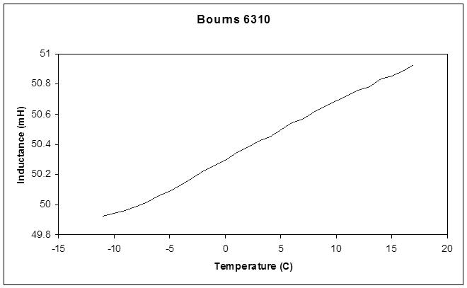
I've had good results with putting the inductor in the freezer for 1/2 hour, pulling it out and sticking a thermocouple on it and connecting it to an LC meter, then monitoring the L as the temperature rises.  Bourns 6310 drifts about +800ppm/C:

I'd be very interested if you could measure similar data for the TDK inductor.

livio, what do you think about the ferrite rod and RF?  I think anything that concentrates the magnetic field locally will probably reduce emissions.  With this reasoning an air core inductor would be the worst for emissions.

Posted: 3/2/2014 3:24:50 PM
dewster

From: Northern NJ, USA

Joined: 2/17/2012

"My experiments with shielding led me to the following conclusions:"  - FredM

Wow, very nicely summarized Fred, thanks so much!  Obtaining this kind of hard-won info can keep one frittering away in the lab forever.

Since I've never owned more than one Theremin, I have no experience with Theremins interfering with each other.  What are the symptoms?

Posted: 3/2/2014 3:58:39 PM
dewster

From: Northern NJ, USA

Joined: 2/17/2012

"However, your idea to reduce the field is right and should work. You might not get a perfect cancellation, but an attenuation of 20 dB is feasible and would certainly be a good step in the right direction. But the number of inductors should be equal (two or four)"  - livio

livio, I want to apologize to you for my incorrect arguing over RF from a coil.  I'm not an RF guy so it took me a while to see what you were talking about.  The EWS does indeed seem to have a coil loaded, tuned antenna.

And yes, to reduce the coil RF one could use 2 or 4 as you say above and orient them to mostly cancel RF in the far field.

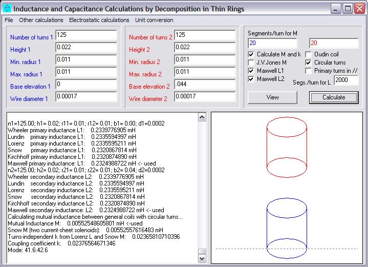
If you have never used it, the transformer program Inca is quite interesting.  You can simulate all sorts of solenoid based coils and transformers with it.  For instance, here are two 0.23mH windings on 1/2" PVC with 34AWG:

Separating them by ~22mm gives around 2.4% coupling (k) or 0.006mH mutual inductance.  Adding the two together gives 0.52mH total, and if they are wound in opposite directions we would subtract the mutual inductance, which gives around 0.51mH.  Something like this could dramatically reduce RF emissions and would be very easy to construct.

Posted: 3/2/2014 4:26:50 PM
livio

Joined: 2/2/2014

"Theremins interfering with each other.  What are the symptoms?"

The symptoms are that when the frequency becomes the same (similar hand position and similar base frequency oscillators) moving the hand on the first Theremin there is a position that affects the frequency of the second Theremin. If they are very near the two frequencies can also be locked for a large range of hand positions. 

"...putting the inductor in the freezer for 1/2 hour, pulling it out and sticking a thermocouple on it and connecting it to an LC meter..."

Sorry, I never done tests on the TDK inductors because of the lack of a precise meter like your. Maybe you could by a TDK -NL453232T-331J from Mouser and test it...  

I think also that the inductor test is not very significative. I prefer to test the complete device and hear the sound produced. With our CapSensors it is possible to heat all the device with a Hair Drier about 10 degree with very little frequency changes (less then 10 Hz). Also with 20 or 30 degree the player can continue to play without notice the frequency change. This is not only due to the inductor, we do not use the heterodyning, so do not amplify the oscillator and inductor defects and noises. Not using Heterodining also poor inductors are OK.

If the temperature changes are really strong (say from -10 to +30 degree) a single click software tuning restores the zero in a fraction of second. The good of our solution is that there are not hardware trimmings at all. Please test an EW with an Hair Drier I think that it will change so much than it will require also a hardware tuning to restore a normal working situation.

"I think anything that concentrates the magnetic field locally will probably reduce emissions.  With this reasoning an air core inductor would be the worst for emissions."

It is not necessary a cylinder enclosing all the bobbin, there are also other good topologyes like toroids or "U" closed with "-". But Magnetic lines must be closed by a good magnetic path. If the path is not closed then air or ferrite bobbins are about the same, they emit a strong magnetic field. I think that very good results could be obtained with a good RF toroid with very low AL (AL is uH for 1 turn). Toroids made with ferrite with AL = 0.1 are incredibly stable with the temperature. But I think also that TDK is more able that us to make perfect inductors...   

Maybe tomorrow I will compose my LC meter. I use a square wave generator a bridge and the scope to mesure low inductors with precision. And, maybe I will do your freezer test on the TDK inductors.

Posted: 3/2/2014 4:40:40 PM
livio

Joined: 2/2/2014

"Separating them by ~22mm gives around 2.4% coupling (k) or 0.006mH mutual inductance.  Adding the two together gives 0.52mH total, and if they are wound in opposite directions we would subtract the mutual inductance, which gives around 0.51mH.  Something like this could dramatically reduce RF emissions and would be very easy to construct."

I would be very surprised if you could in this way to do better than a single little SMD inductor, TDK has learned for decades how to make good coils. 

The idea that ferrite is not stable is a legend. The ferrites with low permeability are perfectly stable and enable such a reduction of the number of turns that the problems due to the elongation of the wire disappear. A good manufacturer such as TDK also blocks the movement of the wire with a temperature stable resin. You can not do these things DIY.

The new NLC models (NL453232T-331) have also improved shielding for which the field that comes from them is practically zero. You could try them before you spend a lot of time doing coils difficult to reproduce. Or, if you prefer a DIY solution, you could use a toroid that closes perfectly the magnetic lines.

I am preparing the LC meter and the freezer ;)


Posted: 3/2/2014 5:00:04 PM
dewster

From: Northern NJ, USA

Joined: 2/17/2012

"I would be very surprised if you could in this way to do better than TDK, they have worked for decades to make good coils."  - livio

TDK can certainly make a better surface mount closed ferrite coil than I can, but they are making these parts for miniature choke applications (disk drives, PC equipment it says in the datasheet) not Theremins. 

Since I'm not hindered by size constraints, I can make a perfectly fine air core that has higher Q, better temperature stability, and lower self capacitance.

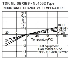
I found some temperature data for the TDK part:

http://media.digikey.com/pdf/Data%20Sheets/TDK%20PDFs/nl4532.pdf

From the chart at the end it looks like 1% inductance change for a 60C temperature change.  0.01/60=167ppm/C.  Better (5x) than Bourns but still not very good.  Q=40 which is OK I suppose.  Self-resonance=3.5MHz which is rather close to your operating point.

Winding my own on 1/2" PVC with 34AWG gives almost no measurable temperature dependence (with my limited equipment), Q=418@2.5MHz, Self-resonance=9.3MHz. 

Except for RF, I win!

"The idea that ferrite is not stable is a legend."

I've found that most ferrite is crap for digital Theremin use, particularly with no temperature compensation.  I may use ferrite chokes for the volume side, but would like to avoid using them on the pitch side.

[EDIT] Looking back in my notes, I measured a large 6.18mH air core solenoid I wound as having ~20ppm/C, but this was at the very limits of my measurement ability.

Posted: 3/2/2014 5:52:46 PM
livio

Joined: 2/2/2014

Waoo thanks! This data sheet is very interesting I have not found it before!

TDK_NL4532_InducVsTemp

I am working with the inductance meter to test this myself. I will post the results here in 1 or 2 hours.

I am not using the freezer but making heating cycles so I can go more speedy and make many cycles in some hour. I increase the temperature to 60 .. 70 degree with the hair drier. Then Measuring with a LaCrosse CN4 V01 infrared temperature meter (not precise but OK for this) I wait that the temperature decreases to 50 degree and write the impedance on a paper. Then waiting 15 minutes the temperature decreases about to the ambient (18 degrees) and when I read 20 degree I write the impedance on the paper.

I am in the middle of the second cycle...

You must be logged in to post a reply. Please log in or register for a new account.