Let's Design and Build a (mostly) Digital Theremin!

Posted: 3/10/2014 1:17:21 PM
dewster

From: Northern NJ, USA

Joined: 2/17/2012

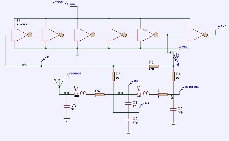
"Here you can download a simplified version of your circuit with the following advantages:"  - livio

Thanks!  Hmm.  The 0.1pF capacitor seems like it might be a problem.  Interesting to see the simplified drive topology as transistors often hide this.

==============

"WISC" + THEREMINO = SPECIAL BLEND OSCILLATOR

I woke up too early thinking about the combined sense / drive in livio's Theremino oscillator, and wondered if it could be combined with the Wiggly Inductor / Split Capacitor (WISC technology!) tank of my oscillator.  This approach would provide the best sensitivity possible because the sense / drive would be across the large, low voltage swing capacitance, and pure antenna capacitance could form the other end with no sense circuitry loading it down.  It seems to spice OK with an ideal inductance, it provides plenty of voltage boost, and it self-starts:

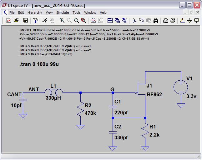
In simulation I'm seeing >100V p-p at the antenna, and a whopping 4.3%F/pF sensitivity.  I've played around with the values some, but not a ton so it's likely not optimal.  And who knows what it will do in reality, but it seems quite promising.  ESD protection of the gate might be problematic because it swings below ground.  FET model is now included in the schematic, and the data collection starts farther out to let the oscillations build to max.  I removed the initial condition to test self-starting.

LTSpice file here: http://www.mediafire.com/download/k9x1zaim9b0538c/new_osc_2014-03-10.asc

[EDIT] Found some MPF102 FETs in my junk box, found a Spice model for it* on the web.  With a few circuit adjustments (C1=100pF, C2=220pF, R1=1k) it is oscillating on my bench at 580kHz with an air-core inductor I had laying around.  Seems a bit less stable than my previous oscillator, but noticeably more sensitive.

[EDIT2] Plugged my 0.5mH air-core into it and it's oscillating at 2.63MHz, something I couldn't get my previous oscillator to do.  I'm sold!  Thank you so much for your help livio!

[EDIT3] With this oscillator topology, an air-core this small, and the simple low impedance series connection between them, one could incorporate the tank inductor as part of the antenna assembly.  This might boost sensitivity a bit more as the coil would then be part of the sensing area.  Doing this, and if using a UHF or other coaxial connector for the coil + antenna, one could also likely ground the outer part of the connector without disturbing things too much.

===========

*.MODEL MPF102 NJF(VTO=-3 BETA=1.304000e-03 LAMBDA=2.250000e-03 IS=33.570000e-15
+ISR=322.400000e-15 ALPHA=311.7 VK=243.6 RD=1 RS=1 CGD=1.600000e-12
+CGS=2.414000e-12 M=.3622 VTOTC=-2.500000e-03 BETATCE=-0.5 KF=9.882000e-18)

Posted: 3/10/2014 5:12:27 PM
FredM

From: Eastleigh, Hampshire, U.K. ................................... Fred Mundell. ................................... Electronics Engineer. (Primarily Analogue) .. CV Synths 1974-1980 .. Theremin developer 2007 to present .. soon to be Developing / Trading as WaveCrafter.com . ...................................

Joined: 12/7/2007

" This approach would provide the best sensitivity possible because the sense / drive would be across the large, low voltage swing capacitance, and pure antenna capacitance could form the other end with no sense circuitry loading it down. " - Dewster

Yeah - its real neat! - I love the "drive-side" sensing, and a small unidirectional low C overvoltage protection device between supply and gate, to restrict gate +Ve to supply and limit -Ve, combined with discharge or other device on the antenna makes this design easy to protect.

It is IMO as good or better than your last!

There are still reasons I love your last (particularly when using 5 of the lower gain unbuffered inverters) - Using the unbuffered inverters one can tap beautiful clean low-Z sine waves, not much use for digital, but great for analogue.. Having low-Z sines and square one can distort and shape pre-mixer, and having this from such a stable oscillator, makes your last a classic for analogue IMO.

Fred.

Posted: 3/10/2014 5:25:29 PM
livio

Joined: 2/2/2014

This is a true real step in the good direction. Many many thanks to be so collaborative.

---------------

In the meantime I have tested your precedent DewsterV2 with real OpAmps and found that it was working only beacause of the used "Level2" operational with unrealistic parameters (GBW=100Meg Slew=100Meg)

No real operational works well in your DewsterV2 and also in my DewsterLivioV3, only very fast operationals like LM118 are oscillating, but with so poor characteristics that now I think impossible to make good oscillators in the 2 to 3 MHz band with OpAmps.

This new circuit LOOKS VERY INTERESTING, now I will test it for some time.

----------------- 

For some test the MPF102 is OK but please notice that the BF862 has 7 times greater transconductance 45 mS instead of 5 mS and this can facilitate the circuit design. In addition, the recent construction of FET are much more robust, almost as transistors. The BF862 is absolutely the best in these circuits.

Never seen a BF862 damaged because our CapSensors have a little input capacitor and the inductor to GND.

With schematics where the inductor is not grounded we will find some good ESD solution. Probably the best protection will be two diodes, Gate to VCC and Gate to GND. Or even only one, between Gate and GND, because the Gate itself act as diode when the voltage goes too much high.

------------------

[Edit1] Your new oscillator looks very beautiful. Why do not we have thought of us before? Thank you for having been so patient with me!

[Edit2]  "The 0.1pF capacitor seems like it might be a problem."   Yes a 0.1 pF is absolutely unrealistic, it is possible to emulate it with two capacitors or 1 capacitor + 1 resistor. But I do not suggest to follow this circuit, it was only an example using the unrealistic parameters (GBW=100Meg Slew=100Meg).


Posted: 3/10/2014 6:15:12 PM
FredM

From: Eastleigh, Hampshire, U.K. ................................... Fred Mundell. ................................... Electronics Engineer. (Primarily Analogue) .. CV Synths 1974-1980 .. Theremin developer 2007 to present .. soon to be Developing / Trading as WaveCrafter.com . ...................................

Joined: 12/7/2007

" I have tested your precedent DewsterV2 with real OpAmps and found that it was working only beacause of the used "Level2" operational with unrealistic parameters (GBW=100Meg Slew=100Meg) No real operational works well in your DewsterV2 and also in my DewsterLivioV3, only very fast operationals like LM118 are oscillating, but with so poor characteristics that now I think impossible to make good oscillators in the 2 to 3 MHz band with OpAmps." - livio

I think the above is a good advice / cautionary warning.

In a forum like TW, where people of different levels of competency are looking at the postings, it is easy for a newbee to make the above mistake.

EE's and those familiar with simulation would instantly recognise that the ideal opamp in Dewsters circuit (and also the resistors to generate its bias) was simply a method of aproximating a gain stage, and no competent EE would ever dream of substituting a real opamp in that simulation or circuit. The "opamp" is easily replaced with a low cost gain stage that is far cheaper than almost any op-amp (certainly cheaper than the HF opamp that would be required to replace the "ideal") - I used a low cost ubuffered CMOS hex inverter, other low cost solutions are available.

Dewster did say that the opamp would be replaced with some other component, probably CMOS - But perhaps he didnt say it loudly enough... Before we know it TW could be swamped with newbees who have tried to build his oscillator using an LM358 or something similar !

The lesson here is perhaps we need to have a big red warning over every simulation when any simplified part or model that cannot be bought is used in the simulation.

Fred.

Below is the schematic from my simulation, with the opamp replaced by a 74HCU04 - I happened to have built a model for this part (a true analogue model employing the circuitry, MOSFETS with charactaristics close to the CMOS parts, and protection components) , if I didnt have it, I would have used an ideal opamp like Dewster did. Oh, R3 and R4 are to simulate inductor resistance - again, the kind of thing that can confuse a newbee unless specifically mentioned, as they are likely to think they need to add these components!

WARNING TO CONSTRUCTORS / EXPERIMENTERS - This is NOT a circuit to build - its a SIMULATION! - Theoretical only ! - May work, may not, has components you wont need, may need components not shown!

Posted: 3/10/2014 6:52:49 PM
livio

Joined: 2/2/2014

"would instantly recognise that the ideal opamp in Dewsters circuit (and also the resistors to generate its bias) was simply a method of aproximating a gain stage"

If the need is "aproximating a gain stage" then there are better SPICE elements than a strange OpAmp. I prefer to use always real components, with real names, with all the parameters simulated at the best. Or it is very easy to create monsters.

Downloading my libraries, in the folder "74HC", there are good approximations of 74HCU04, 74HC14, CD40106 and CD4093

[EDIT 1] But I not suggest to use CMOS digital components because of the high instability of the frequency produced by their very high noise in the band below 10 Hz.

[EDIT 2] However, now I will try with a DewsterV2 with a 74HCU04 to see how it can work.

[EDIT 3] Yes, with a 74HCU04 it works with sensitvity = 3.3% F/pF (a little more than CapSensor 2.7% F/pF)

[EDIT 4] If you are interested to 74HCU04 oscillators this is more simple, has more sensitivity (4.2% F/pF) and more voltage on the antenna (110 Volt p.p.) --- To simulate it our libraries are needed.


Posted: 3/10/2014 8:11:30 PM
FredM

From: Eastleigh, Hampshire, U.K. ................................... Fred Mundell. ................................... Electronics Engineer. (Primarily Analogue) .. CV Synths 1974-1980 .. Theremin developer 2007 to present .. soon to be Developing / Trading as WaveCrafter.com . ...................................

Joined: 12/7/2007

"If the need is "aproximating a gain stage" then there are better SPICE elements than a strange OpAmp." - livio

The ideal opamp model has some big advantages over spice primitives like the VCVS etc - for one thing, it can only output voltages limited by the supply rails to the opamp - VCVS with gain will output absurd unrestrained voltages, so to make any realistic model one would need to add other clamping / limiting components.

Using the ideal opamp model for simulations of the kind Dewster presented is standard practice, and there arent actually any "drop in" models in the spice arsenal which do the job better for this kind of simulation.

Fred.

Posted: 3/10/2014 8:56:41 PM
dewster

From: Northern NJ, USA

Joined: 2/17/2012

"This is a true real step in the good direction."  - livio

I certainly hope so.  On paper it checks all the boxes of my dream oscillator, but in reality it may not be optimal.  In the past I've noticed a strong correlation between sensitivity and instability with my oscillators.  An unstable oscillator is pretty much useless.

"Many many thanks to be so collaborative."  - livio

Thank you for revealing all you do here and on your excellent web pages!  This field is tiny, so if we all work together we can move ahead much faster.

"I think the above is a good advice / cautionary warning."  - FredM

Thanks!  I made the text red and made it more explanatory and cautionary.

"The ideal opamp model has some big advantages over spice primitives like the VCVS etc - for one thing, it can only output voltages limited by the supply rails to the opamp - VCVS with gain will output absurd unrestrained voltages, so to make any realistic model one would need to add other clamping / limiting components."  - FredM

Yes, this is exactly why I used an idealized opamp - to limit output swing to the rails.  I lowered the open loop gain to 100, and jacked up the GBP and out slew rate, figuring that's close to what CMOS kind of does.

"Downloading my libraries, in the folder "74HC", there are good approximations of 74HCU04, 74HC14, CD40106 and CD4093"  - livio

Thanks!  I downloaded them and will give those inverters a try.  I found one model on the web but the VT parameters were obviously wrong so I was afraid to use it.

Posted: 3/10/2014 9:29:48 PM
FredM

From: Eastleigh, Hampshire, U.K. ................................... Fred Mundell. ................................... Electronics Engineer. (Primarily Analogue) .. CV Synths 1974-1980 .. Theremin developer 2007 to present .. soon to be Developing / Trading as WaveCrafter.com . ...................................

Joined: 12/7/2007

"[EDIT 4] If you are interested to 74HCU04 oscillators this is more simple, has more sensitivity (4.2% F/pF) and more voltage on the antenna (110 Volt p.p." - livio

Thanks livio -

I dont have time right now to fully evaluate this - but the thing I like about Dewsters oscillator is its purity - As I see it, using unbuffered CMOS to replace the "opamp" one ends up with a completely linear (analogue) oscillator..

IMO, the major "problem" with CMOS oscillators (if there really is a noise problem with them) is likely to be "threshold noise" - When unbuffered inverters are run with over-all -Ve feedback and are effectively forming a gain stage with no switching, then, as I see it, any potential "noise" problems are eliminated or at least hugely reduced - The final inverter sees a large signal, so it can act safely as a switching device to produce the logic level output.

Dewster earlier mentioned his hypothesis that perhaps CMOS "noise" was due to interaction of elements sharing the same IC supply (I am paraphrasing here - cant really remember exactly what he said ;-) and I think this could be really relevant when elements are switching, because any noise on the supply will directly influence the thresholds of those elements.

When elements are running in their linear mode, and there are no switching events on the part (for best operation removal of even the single switching output inverter may be best) then I think one may get extremely good performance. But your simple oscillator looks like it might be "noisy".

Our objectives are different - I dont care if I "waste" a few components - dedicating a whole hex inverter to a single oscillator, and having perhaps a seperate comparator on the output if I want to drive logic, doesnt bother me at all.. I like simple, but opt for more "complex" if "simple" doesnt give me everything that im after.

"Yes, this is exactly why I used an idealized opamp - to limit output swing to the rails.  I lowered the open loop gain to 100, and jacked up the GBP and out slew rate, figuring that's close to what CMOS kind of does." - Dewster

Your model worked great! - My "real" 74HCU04 behaviour in your oscillator was extremely close to your opamp model, and when it comes to models, they are all just models - one cannot rely absolutely on any of them.

"because the Gate itself act as diode when the voltage goes too much high." - livio

Yes, it does! - And this is one of the primary mechanisms by which a FET is destroyed! - Its not capable of surviving high gate currents, and will be damaged and its performance permanently degraded  even if the part isnt completely destroyed - one needs an external "bypass" component/s of some kind to protect the gate from this event and from any other event (gate excessively -Ve for example) which causes gate voltages or currents to exceed the parts specification.

Fred.

Posted: 3/10/2014 10:36:56 PM
dewster

From: Northern NJ, USA

Joined: 2/17/2012

"For some test the MPF102 is OK but please notice that the BF862 has 7 times greater transconductance 45 mS instead of 5 mS and this can facilitate the circuit design. In addition, the recent construction of FET are much more robust, almost as transistors. The BF862 is absolutely the best in these circuits."  - livio

Do you know of a thru-hole device I could use in my breadboard that would be similar to the BF862?

Oh, and forget everything I said about a second inductor in series with your parallel tank (I went back in this thread and edited my recent comments regarding this).  I just quickly spiced it and it gives the same crazy double resonance the EWS has.  Works great for series tanks though, it increases sensitivity and voltage swing by a factor of ~1.5.

Posted: 3/11/2014 12:31:42 AM
dewster

From: Northern NJ, USA

Joined: 2/17/2012

"I dont care if I "waste" a few components - dedicating a whole hex inverter to a single oscillator, and having perhaps a seperate comparator on the output if I want to drive logic, doesnt bother me at all.."  - FredM

The LVC1404 is made exactly for this.  Three inverters: two in series with access to the middle connection, and a third inverter with hysteresis for output buffering.  Marketed for use in crystal oscillators.

One thing that slightly bugs me about single FET oscillators is that they run class A.  Which means they aren't the most power efficient.  Which means they have to heat up a bit before they're stable.

You must be logged in to post a reply. Please log in or register for a new account.