Let's Design and Build a (mostly) Digital Theremin!

Posted: 6/20/2014 12:27:06 AM
dewster

From: Northern NJ, USA

Joined: 2/17/2012

"Do you really need to?"  - FredM

Well, I know I could be accused of retiring on this project, but it's giving me a lot of practice with a bunch of stuff including digital filtering.  And quick setup stuff probably isn't too possible at this point, although there is always a huge value in it.  Maybe I should try everything in Hive and ditch most of the special hardware - gotta keep the 8 threads busy doing something. 

"I dont see the theremin going into "the dustbin"

As usual you've articulated this much more clearly than I am capable of doing and I completely agree with your assessment!  The Theremin likely won't disappear at this point, though IMO unless there are fundamental changes it will likely remain somewhat obscure. 

It seems that octaves on a Theremin are something like megapixels on a digital camera - beyond a certain level they degrade functionality, though they look good on paper.

=========

Played around in simulation today with the zero crossing LPF following the XOR heterodyning.  A cascade of two simple first order IIR sections works pretty well, though it is straining a bit at the two extremes.  A third section tames it a tiny bit better.  These are fairly trivial at the hardware level, though it would be nice if there was some kind of tracking going on.

Posted: 6/25/2014 2:18:45 PM
dewster

From: Northern NJ, USA

Joined: 2/17/2012

So here is what I'm simulating in Excel:

It seems a bit of high pass filtering is necessary post heterodyning in order to center up the thresholding after low pass filtering.  Three stages of simple first order low pass give pretty good results over a fairly wide range of input frequencies.  It's too bad I can't get the LC sine wave into the FPGA as this would really reduce the filtering requirements.  But these filters aren't too wide (in terms of bits) so maybe it's not too big a big deal.  The low pass filter after the period measurement is variable rate, the advantages of which were previously discussed.  The final filter is fixed rate, and I'm wondering if some kind of recursive arrangement could be employed here over multiple clocks, as this filter runs at a fairly low rate for the FPGA hardware.

[EDIT] Just wanted to add, for a 160MHz system clock, the HPF attenuation factor of 2^5 corresponds to a corner frequency (-3dB) of ~800kHz, and the LPF corner frequencies are similarly ~400kHz (though cascading three of them like this significantly lowers the -3dB point).  The 2^8 factor at the beginning gives the filters large enough data to "chew on" (significantly increases resolution) and isn't a real multiplication per se as it is simply multiplied by the input +/-1.

Posted: 6/25/2014 10:09:41 PM
FredM

From: Eastleigh, Hampshire, U.K. ................................... Fred Mundell. ................................... Electronics Engineer. (Primarily Analogue) .. CV Synths 1974-1980 .. Theremin developer 2007 to present .. soon to be Developing / Trading as WaveCrafter.com . ...................................

Joined: 12/7/2007

Hi Dewster,

Yeh - that looks good!  Had me a bit confused at first - was thinking analogue ;-) .. But having a variable and fixed LPF working on the period data (after period measurement) makes a lot of sense.

In terms of FPGA implementation, everything (except LCO) on the diagram is in the FPGA, with only the fixed-rate data from LPF b going to the processor - so there is no processor intervention (?) and you get all the advantages of heterodyning with none of the peripheral analogue hardware..

Real neat, real tidy, huge potential for tweaking without changing components.. You have an NCO that can presumably be adjusted as required.

But I do get a pain between my ears when I look at some things you do ;-) ... I see a schematic, with an XOR taking two inputs and giving a pulse output... To me, its "real" and the 2^8 got me thinking it couldn't be "real" but must all be somehow "numerical" LOL ;-)

So lets see if I got it... its 2^8 multiplied by 0 or 1 (XOR pulse output) - effectively 8 * 2 input AND gates, each having one input tied high (1) and the other inputs all commoned and connected to the XOR output, so when the XOR output is high, you get 0xFF into the HPF, and when the XOR output is low you get 0x00 into the HPF. ... (Actually, I got that wrong.. its a bunch of XORs and a signed result going to the HPF)

This increased "amplitude" is then easier to process by the following HPF and LPF's, and the period measurement block looks at the numerical result from the final LPF and produces its period count after determining the crossing points from its incoming data...

And each of these blocks is coded - no schematics, "just" Verilog ++ or whatever...

Really impressive stuff IMO!

Fred.

Posted: 6/26/2014 5:08:27 PM
dewster

From: Northern NJ, USA

Joined: 2/17/2012

"...so when the XOR output is high, you get 0xFF into the HPF, and when the XOR output is low you get 0x00 into the HPF. ... (Actually, I got that wrong.. its a bunch of XORs and a signed result going to the HPF)"  - FredM

Yes.  If you flip the MSB you get signed, so signed or unsigned is rather trivial / arbitrary.  I picked signed so that the thresholding and accumulator initialization is conceptually simpler (@ zero rather than 1/2 the max, though both are just the MSB).

Gates are mainly for human convenience as the tool blends it all together and boils it back down to LUTs.  This is what I really like about HDL programming: all the tedious Karnaugh mapping and state machine state assignment and reduction and decoding is done automatically and 99% of the time much better than I can do (particularly from a global perspective).  One should be aware of this stuff, but much of what we spent months slaving over in school is otherwise rather moot.  (I remember finding BJT bias points to 3 decimal places via iteration, something one would never do in real life because device parameters tend to be terribly sloppy.)

"In terms of FPGA implementation, everything (except LCO) on the diagram is in the FPGA, with only the fixed-rate data from LPF b going to the processor - so there is no processor intervention (?) and you get all the advantages of heterodyning with none of the peripheral analogue hardware..

Real neat, real tidy, huge potential for tweaking without changing components.. You have an NCO that can presumably be adjusted as required."

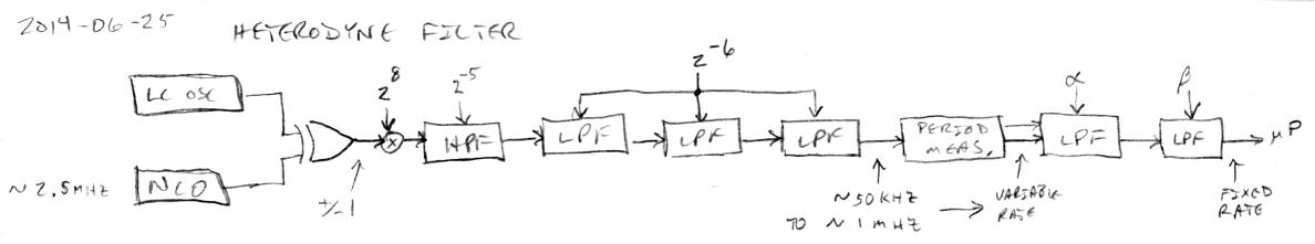
It seems to work quite well (in simulation) over a large range (~10kHz to ~1.3MHz).  The processor will have to get involved in setting the NCO frequency.

Playing with it a bit more this morning the initial multiplication should perhaps be 2^9 to get better resolution at lower frequencies, though of course putting it in HW will be the true test.  I'm also thinking the variable rate filter could be second order, and the final fixed rate filter perhaps dispensed with.  Have the processor sample it at 50kHz or so, which would give 400 instructions for the thread (running at 20MHz) to do something with the sample like more sophisticated LPF and perhaps 50/60Hz high Q notch.

I've done this kind of circuit in the past for products, but with no heterodyning, and with a single LPF after the period measurement, to measure the "frequency" deviation of an input (actually period deviation, but the two are quite close for small deviations about nominal).

"Verilog ++ or whatever..."

I can't believe they changed the name to SystemVerilog when it's really just an update to Verilog and not a new language at all.  The name change is what kept me away from SV - that, and the way SV is "sold" as a primarily for verification and not synthesis so much, which is also quite deceptive.  And this is my field!  Gaaa!

Posted: 6/30/2014 8:13:16 PM
dewster

From: Northern NJ, USA

Joined: 2/17/2012

Coded the above in verilog (SV) using ~2^10 for the XOR gain into the HPF.  Simulation is a bit painful, but 1ms of sim time isn't too terrible, maybe a minute or so of real time.  Seeing more or less expected operation from 30kHz to 900kHz (heterodyned frequency) with glitching (false periods) above and below.  For period measuring I'm measuring rise-to-rise and fall-to-fall separately and kicking them out sequentially, for two samples per cycle.  The output filter shows the expected corner frequency tracking.  Top speed of the logic is just a bit above 160MHz which is my target.

This range of this whole arrangement is strongly governed by glitching limits.  Both ends kind of scare me - the low end could drift down from the nominal 50kHz, a hand too close to the antenna might push it too high.  I wish there were some way to get auto-tracking of the cutoff working previous to the period measurement.  Maybe I shouldn't be trying for so much heterodyning difference, but 2.5MHz mixed down to 50kHz (far field) gives pretty flat linearity in simulation.  I get the feeling I'll be linearizing in SW, so I'm not sure why I'm fighting so hard for this to work out "naturally" when a stray pF or two at the antenna can blow it out of the water.

Posted: 6/30/2014 8:30:11 PM
FredM

From: Eastleigh, Hampshire, U.K. ................................... Fred Mundell. ................................... Electronics Engineer. (Primarily Analogue) .. CV Synths 1974-1980 .. Theremin developer 2007 to present .. soon to be Developing / Trading as WaveCrafter.com . ...................................

Joined: 12/7/2007

"Both ends kind of scare me - the low end could drift down from the nominal 50kHz, a hand too close to the antenna might push it too high." - Dewster

Perhaps you could implement bound checking rather auto-tracking? Ok, it would eat some of the FPGA resources, but if you checked the incoming (VFO) frequency against max and min values (window phase / frequency detector) and flagged an out-of-bounds condition (which perhaps locked the last trust-worthy values) it may be easier to manage.

Its certainly easy to implement a logic frequency 'comparator' if one has actual frequencies - the way I did it on my H1's was daft (I used the MCU to actually compare counter values) - since then I have used register based phase comparators feeding analogue integrators (specifically because I didnt want sharp limits) .. I suspect an all logic scheme would be simpler.

Really sounds like you are getting close ;-)

" I get the feeling I'll be linearizing in SW, so I'm not sure why I'm fighting so hard for this to work out "naturally" when a stray pF or two at the antenna can blow it out of the water."

Because, dear Eric, you share one personality feature common to all theremin developers - Some degree of Obsessive Compulsive Disorder! ;-) ... Oh, I think most of us are sub-clinical, but unless we were a bit OCD we would have walked away from theremins within the first year. Add to this the fact that (whether you realize it or not) you are a perfectionist, and that explains most of the reason... But its not only that - You know damn well that the better the front-end is, the more reliable the product will be.. Its a GIGO situation - sure, get garbage in, and with some processing what comes out may not be garbage.. But eliminate (or reduce) the input garbage, and the processing is reduced and what comes out is likely to be "better".

Fred.

Posted: 6/30/2014 10:17:02 PM
dewster

From: Northern NJ, USA

Joined: 2/17/2012

"Perhaps you could implement bound checking rather auto-tracking?"  - FredM

Yes, but the problem areas are relative rather than absolute due to heterodyning.  I suppose I could make them relative / absolute but the bounds would be rather arbitrary inputs by me.

"You know damn well that the better the front-end is, the more reliable the product will be.. Its a GIGO situation..."

Yes, all too aware!  What's getting me is that offset heterodyning with period measurement gives a golden opportunity to linearize the near field.  My numerical linearization solution depend on a mid-field number that it is rather sensitive to (though it can be re-used as the sensitivity "tilt" point).

For instance:

Above is a simple LC oscillator with 3pF stray beating against an NCO to give 50kHz beat far-field.  Basic linearity is quite good.

Above I've increased the far-field beat frequency to 100kHz (blue line), and then applied some numerical linearity correction (red line).  Far-field linearity is better, but is the average person able to do this kind of adjustment?  Will drift throw a monkey wrench into it?

Above I've increased the stray capacitance to 30pF and adjusted far-field beat to 5kHz to compensate.  No numerical linearity adjustment.  Linearity is again very good.  We're killing sensitivity with stray capacitance and getting it back via more aggressive heterodyning, which should make drift worse.

Anyway, bringing the whole thing into alignment might be as simple as moving the far-field beat point, which is really hard to ignore.

Spreadsheet is here: http://www.mediafire.com/download/bvvvm2yyl5bw7f9/Rod_2014-06-17.xls

Posted: 6/30/2014 11:43:11 PM
FredM

From: Eastleigh, Hampshire, U.K. ................................... Fred Mundell. ................................... Electronics Engineer. (Primarily Analogue) .. CV Synths 1974-1980 .. Theremin developer 2007 to present .. soon to be Developing / Trading as WaveCrafter.com . ...................................

Joined: 12/7/2007

"Anyway, if one can stay away from numerical linearization, bringing the whole thing into alignment might be as simple as moving the far-field beat point." - Dewster

It does look that way! - Hell, the 0.1 to 0.55 is so linear people wont like it! LOL ;-) .. You may need to add numerical "linearization" to give folks the non-linearity they are used to ;-)

Dewster, if the linearity is even close to what these sims are predicting, its time, IMO, for you to move on to the next step (before you become like me - an aging nerd with loads of "knowledge" about one niche area, who has almost given up on ever producing an instrument, and gets more isolated and pedantic and distracted and bitter and twisted by the day) - With conventional analogue heterodyning theremins its not possible to move the null point in order to get linearity improvement as the bass is always close to this point.. But having the flexibility to do this digitally changes the rules completely.

"Yes, but the problem areas are relative rather than absolute due to heterodyning.  I suppose I could make them relative / absolute but the bounds would be rather arbitrary inputs by me."

Does it matter? You have a huge span available between the extremes where problems start - If you set arbitrary bounds that ensure you never get into the danger zone, and set the instrument up so its extremely unlikely to ever get into this zone, ok - you may throw away perhaps 20% (?) of available resolution - but if you can spare this, you should be ok... Alternatively, is there any way to auto-detect the level of glitching (asymmetry or whatever) and lock the values when this exceeds some threshold/s?

"We're killing sensitivity with stray capacitance and getting it back via more aggressive heterodyning, which should make drift worse."

I dont see this - sorry, we've been here before ;-) - Also, not really sure I understand the source of this "stray capacitance"  - except that you are (?) effectively increasing the sensitivity at the far-field end, and as such, there will be more capacitive "noise" ... But any and every scheme that linearizes this area must effectively do so by increasing the far-field sensitivity - in fact, isnt this what "linearization" really boils down to - decreasing the near-field and increasing the far field sensitivities in a controlled manner ..?

I have been using this as the principle means of linearization - effectively making the VFO less sensitive to capacitance change as its frequency drops, and more sensitive as its frequency increases - all done in analogue by monitoring the VFO frequency using a BPF and generating a CV from this which is processed and fed back to the VFO - but I only need to go this awkward route because I still haven't had the guts to break free from combining the front-end with the sound engine - You are free from such constraints, and the scheme you are using is probably more linear than is actually 'needed' even without any number crunching, and even if it wasnt working at optimum due to poor capacitive environment.

Fred.

Posted: 7/1/2014 5:04:51 PM
dewster

From: Northern NJ, USA

Joined: 2/17/2012

Comedy of errors in my verilog code, ironed them out this morning and the results are much more in line with the Excel simulation.  So now I'm seeing operation from 10kHz to 1.3MHz (heterodyned frequency) with glitching (false periods) above.  It maybe even looks OK at 5kHz but I'm not simulating long enough to see that very well, and I've got the period measurement maxing out at 20kHz.  This is more than a 1:100 range which makes me feel less nervous about how it might work in real-life.

"Alternatively, is there any way to auto-detect the level of glitching (asymmetry or whatever) and lock the values when this exceeds some threshold/s?"  - FredM

That's similar to the protections they put in communications PLLs, where the impairment detectors have to respond more quickly than the PLL and perhaps restore it to a state in the recent past in order to center it at a more reasonable point than the current deviation.  Here we're talking a difference of maybe 5kHz in 2.5MHz (2000 ppm) which could take a while to dependably resolve and threshold with a 160MHz clock.  In the PLL case it's doable with a period measurer feeding a LPF (speed/resolution tradeoff), with the bandwidth of the detector set significantly higher than that of the PLL.

In my period measurer there is a "debounce" period in the state machine that keeps it from responding to input edges that are too close to the edge it just responded to, and which also flags bounce events.  I could add a bit of hysteresis, but that would likely roughen up the period measurement, and wouldn't likely improve anything else much.

"Also, not really sure I understand the source of this "stray capacitance""

Just throwing a wrench into it to see what can be accommodated.  Probably not very optimal with that much capacitance loading down the antenna and swamping hand capacitance, but it's interesting that lowering the beat seems to restore linearity.

Posted: 7/2/2014 3:42:59 PM
dewster

From: Northern NJ, USA

Joined: 2/17/2012

The filtering following the period measurement is kind of sticking in my craw.  To measure the period, we are counting system clocks between rising edge events.  The simplest filtering is averaging.  So to average multiple periods we could just let the counter go for as many rising edge events as we want averaged, then divide by the number of rising edges that happened during the averaging period.  If we restrict the number of rising edges to powers of two, then the division is a simple right shift of the count, and the shift distance is exactly like the exponential in a floating point number.  The period averaging logic could then be reduced to a clock counter, an edge counter, a power of 2 event counter (which looks at rising edges of the bits which comprise the edge counter), and a state machine.  The machine looks for the accumulated clocks to pass a threshold, and the produces an unsigned float output when accumulated edges reach a power of 2.  This gives us a variable rate filter that is limited to a 2:1 range, increasing resolution with smaller period inputs, and gives us a construct that won't excessively load the processor down with interrupts.  Further filtering to ~1kHz and 50/60Hz hum can then take place in software where it is much more efficient.

This is a cheap and simple 2:1 variable rate integrate and dump filter with variable 2^n cutoff, something I haven't seen in the literature.  Off to watch it fall on its face in simulation...  I'm worried that the cutoff switching might somehow be audible to the user, but I think if processor sampling is kept ultrasonic (in the 50kHz to 100kHz range) then it likely won't be?

You must be logged in to post a reply. Please log in or register for a new account.