Let's Design and Build a (mostly) Digital Theremin!

Posted: 10/19/2014 6:40:05 PM
dewster

From: Northern NJ, USA

Joined: 2/17/2012

After looking at a bunch of other languages I'm back to Python.  The bit manipulations aren't too bad and seem to speed things up over the high level gyrations you are forced to do in Excel VBA.  Just finished describing the ALU as a class and am now debugging it.  The interpreted shell IDLE (I assume ala Eric, as Python is ala Monty?) is really pretty nice for this, just cut and paste your code into it and interact with it via small iterated statements, I wish every language had this exceedingly valuable debug feature.  There's nothing like getting to know your code via simulation.  Like the SystemVerilog description, I made the ALU sim code data width a variable, so even exhaustive checking is simply a matter of reducing the bit width to something narrow like 4 and going to town.

When you do processor simulator design you find out how math oriented languages are rather than hardware oriented - modulo integers have a consistency and magic all their own.  You also find out how complex simple seeming things like add, subtract, multiply - and particularly division - are (with Python v3 they added an int floor division to resolve float & int division situational ambiguity - this broke backward compatibility but at least they addressed the issue). 

When doing math in hardware it all ends up modulo the registered width, and sign is only a convention, so you pick a convention and stick with it.  For instance my ALU simulation code uses signed as the default, and I picked this over unsigned as it makes testing the MSB trivial - in hardware the signed form provides for automatic lead padding.  Some kind of sign extension is always going on even when doing unsigned stuff, our number system notation is biased towards leading zero suppression, so when leading ones are called for (2's complement negative) it seems unnatural.

Posted: 10/29/2014 1:25:29 AM
dewster

From: Northern NJ, USA

Joined: 2/17/2012

They say the two best days in the life of a boat owner are the day you buy the boat and the day you sell the boat.

The TWDNSIN (Theremin which dares not speak its name) has left the building (casa del dewster).

Posted: 10/29/2014 1:33:07 AM
FredM

From: Eastleigh, Hampshire, U.K. ................................... Fred Mundell. ................................... Electronics Engineer. (Primarily Analogue) .. CV Synths 1974-1980 .. Theremin developer 2007 to present .. soon to be Developing / Trading as WaveCrafter.com . ...................................

Joined: 12/7/2007

Its not a bloody theremin!  - the "thing" that dares not speak its name! ok ;-)

Anyway - If you start getting withdrawl symptoms, or find your head starts to clear from unnatural lusts, let us know!

;-)

(I suspect voodoo involvement in said "thing" ! )

LOL ;-)

(hope you didnt lose too many cents in the deal - you didnt tell the buyer it was a thermin I hope.. cause the Karmic price for such a lie is really high! - particularly if you dont have the excuse of ignorance!  ;-)

Posted: 10/29/2014 1:40:09 AM
dewster

From: Northern NJ, USA

Joined: 2/17/2012

"Its not a bloody theremin!  - the "thing" that dares not speak its name! ok ;-)"  - FredM

I stand corrected!  ;-)

TLOWDNSIN = Theremin like object which dares not speak its name

Posted: 10/29/2014 2:03:02 AM
FredM

From: Eastleigh, Hampshire, U.K. ................................... Fred Mundell. ................................... Electronics Engineer. (Primarily Analogue) .. CV Synths 1974-1980 .. Theremin developer 2007 to present .. soon to be Developing / Trading as WaveCrafter.com . ...................................

Joined: 12/7/2007

Well done Dewster -

Its been a particularly severe blow to you and other (digital) theremin developers to have such a fake object attract the attention and reduce your chances of being taken seriously. While earnest discussion and critical evaluation of a few ms latency has gone on here, the last thing I think anyone was expecting was that thing to jump up like a jack-in-the-box, adorned with the sacred logo, and mock these efforts and the whole theremin community (players and developers alike)

But im not going to rant.. ;-)

Have a party - no doubt it will be bitter-sweet, a bit like a divorce party.. I think that thing will cause a bigger divorce in the end, and divorce this community from the things creator.

Fred.

Posted: 10/29/2014 3:44:01 PM
dewster

From: Northern NJ, USA

Joined: 2/17/2012

"hope you didnt lose too many cents in the deal"  - FredM

It didn't cost me too much to buy and sell (maybe $70 all told) and I learned a lot in the process.

As with any product, more complete information in the hands of the consumer will lead directly to more satisfying purchases with fewer disappointing gotchas down the road.  Depending on their needs and desires, the TLOWDNSIN might be just what a particular person is looking for.  I'm not trying to trivialize it by saying this, but it makes for a really great coffee table addition / conversation piece, and rather dramatically demonstrates to the casual "woo-woo" passerby the magic of capacitive sensing.  But due to the clunky calibration, low gestural bandwidth, and linearity issues, I don't think it is the best fit as the first or only Theremin for those who want to play melodically.  IMO.

Posted: 10/30/2014 3:34:30 AM
dewster

From: Northern NJ, USA

Joined: 2/17/2012

Am I delusional?

I spent some time with my Excel simulations today and they seem to be telling two things that are counter-intuitive to my tiny brain. Given a conventional heterodyning analog Theremin (with a series tank where the "EQ" coil is effectively the tank L and the antenna the tank C):

1. I was under the (now seemingly mistaken) impression that decreasing the nominal frequency of the pitch oscillator by increasing the inductance would reduce the sensitivity (octaves per pF). 

2. I was also under the (now seemingly mistaken) impression that increasing the stray capacitance at the antenna would reduce the sensitivity. 

What seems to be the actual case is that once the local oscillator is readjusted for far null, sensitivity and linearity are the same regardless.  All that happens with increased tank inductance and/or increased stray antenna capacitance is that the overall heterodyned frequency gets reduced (like doing a register shift).

If this is true, it likely means all simple Theremin oscillators (those which have only a single inductance) when properly adjusted for null will have identical response in terms of heterodyned octaves per pF, sensitivity, linearity, range, etc. regardless of the inductance value and stray capacitance at the antenna.  The only difference will be in the heterodyned operating point (i.e. the location of the range over which it plays).

Posted: 10/30/2014 7:14:30 AM
FredM

From: Eastleigh, Hampshire, U.K. ................................... Fred Mundell. ................................... Electronics Engineer. (Primarily Analogue) .. CV Synths 1974-1980 .. Theremin developer 2007 to present .. soon to be Developing / Trading as WaveCrafter.com . ...................................

Joined: 12/7/2007

"If this is true, it likely means all simple Theremin oscillators (those which have only a single inductance) when properly adjusted for null will have identical response in terms of heterodyned octaves per pF, sensitivity, linearity, range, etc. regardless of the inductance value and stray capacitance at the antenna.  The only difference will be in the heterodyned operating point (i.e. the location of the range over which it plays)." - Dewster

Not absolutely true me thinks.. Given a 680uH tank, and a nominal 180pF antenna + Tank capacitance, using f=1/(2*pi*sqrt(L*C)) you get:


Capacitance   Frequency   Delta 
pF:   Hz:   Hz/Pf
179   456183.1   1268.94
180   454914.1   1258.409
181   453655.7   1248.024
182   452407.7   1237.78
183   451169.9   1227.676
184   449942.2   1217.708
185   448724.5   1207.874
186   447516.7   1198.173
187   446318.5   1188.6
188   445129.9   1179.154
189   443950.7   1169.833
190   442780.9   1160.633
191   441620.3   1151.554
192   440468.7   1142.593
193   439326.1   1133.747
194   438192.4   1125.014
195   437067.4   1116.394
196   435951   1107.882
197   434843.1   1099.479
198   433743.6   1091.181
199   432652.4   1082.986
200   431569.4  


From the above it can be seen that for a 1pF change in capacitance, sensitivity reduces as the bulk capacitance increases.

So if you were to have a larger 'background' antenna capacitance, and retune the null to that, you will get lower sensitivity than if you could tune null when there was less background capacitance.

Ahh.. But now I see what you are actually saying, and yes, I think you are right...

Alter the inductor value, and the ratio of sensitivity only actually relates to the capacitance.. Changing L to 750uH one gets:


Capacitance   Frequency   Delta     
pF:   Hz:   Hz/Pf    
179   434373.2   1208.273   1.79E-10
180   433164.9   1198.245   1.8E-10
181   431966.6   1188.356   1.81E-10
182   430778.3   1178.602   1.82E-10
183   429599.7   1168.981   1.83E-10
184   428430.7   1159.49   1.84E-10
185   427271.2   1150.126   1.85E-10
186   426121.1   1140.888   1.86E-10
187   424980.2   1131.774   1.87E-10
188   423848.4   1122.779   1.88E-10
189   422725.6   1113.904   1.89E-10
190   421611.7   1105.144   1.9E-10
191   420506.6   1096.499   1.91E-10
192   419410.1   1087.966   1.92E-10
193   418322.1   1079.543   1.93E-10
194   417242.6   1071.228   1.94E-10
195   416171.4   1063.019   1.95E-10
196   415108.3   1054.915   1.96E-10
197   414053.4   1046.913   1.97E-10
198   413006.5   1039.012   1.98E-10
199   411967.5   1031.209   1.99E-10
200   410936.3      

2E-1


If we look at .... No - Not sure... Pick a frequency, get the right L to match the antenna C, and the frequency delta will just be determined by the LC.. so increasing the 'background' will always decrease the sensitivity. With a simple oscillator like this I see no way to increase the sensitivity, only ways to reduce it - ways to reduce it include padding the antenna (which reduces the oscillator frequency), or series connecting a capacitor to the antenna so that its influence is reduced.

Fred.

 Oh - I do agree that all simple oscillators should have identical responses... But they dont have ;-) Frequency of operation and antenna voltages seem to play a big part.. Higher antenna voltages seem needed at lower frequencies than higher frequency ones for example.. But I dont know.. its all voodoo ;-)

I probably wont be 'round for a while.. probably be reachable by email if you get lonely..

good luck! ;-)

Fred.

Posted: 10/30/2014 3:35:32 PM
dewster

From: Northern NJ, USA

Joined: 2/17/2012

I'm confusing things by using the term "sensitivity" in two contexts.  Capacitive padding / stray will definitely reduce the change in frequency due to the movement of the hand.  But post heterodyning with far field null, it seems that one gets the same range of response (in terms of octaves) regardless (but with a bulk shift in frequency).  It is the process of nulling that makes this so.

Here is the spreadsheet I'm using, rather boiled down to the analog (where output frequency = hetereodyned frequency) and digital (heterodyned period measurement with numeric offset) cases:

http://www.mediafire.com/download/n4556tpbzwwtpz3/Analog_Digital_2014-10-30.xls

Which is not to say that one would necessarily desire to load down the oscillator with a ton of capacitance as this would make the actual frequency changes due to the hand smaller, thus likely degrading overall SNR.  (And in the digital case we want maximum absolute - as opposed to heterodyned - sensitivity.)

I think these kinds of false assumptions on my part were what gave me such trouble coming up with a simple linearizing method.  Perhaps logarithmic & exponential processes / data are fundamentally counter-intuitive?

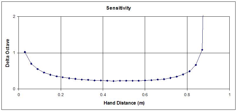
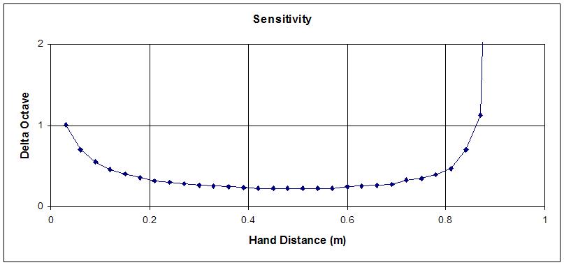
[EDIT] Fred, it stands to reason that reducing the series blocking capacitance between the antenna and tank should reduce heterodyned sensitivity (if properly nulled).  But this doesn't seem to be the case in my more complete simulations where this component is included and the value of it changed:

Above is a simple series LC oscillator with 100pF (top) and 1pF (bottom) blocking C.  The operating point has changed dramatically (not shown here) but the response in terms of octave range and heterodyned sensitivity is virtually identical.

Am I delusional?  This is so counter-intuitive I'm having a hard time accepting it.

[EDIT2] I updated the simple spreadsheet to include explicit tank and blocking capacitance.  This makes the invariant effect described above much more obvious.  This spreadsheet is broadly applicable as a simple (series or parallel tank, no EQ) Theremin design tool:

http://www.mediafire.com/download/tdhhci3q6gs3yuk/Analog_Digital_2014-10-30b.xls

If the above is true, then one could use just about any suitable inductance in any configuration (series or parallel) to build an analog Theremin that would work identically over a variety of ranges.  If the inductance is too small and the resulting heterodyned range too high, then capacitive padding (tank, stray, etc.) could lower it and produce the same response as a larger inductor without the padding.   All within reasonable bounds of course.  And all of which flies in the face of an EQ inductor being necessary(?) for a large pitch field, so I'm kind of stumped when it comes to reconciling this behavior with reality.  Maybe it's just a voltage swing thing?  Time to hit the bench...

Posted: 11/13/2014 1:04:08 PM
dewster

From: Northern NJ, USA

Joined: 2/17/2012

To see the invariant in action, download the spreadsheet above and do the following:

1. On the ANALOG worksheet set "Far Field Null" to 0, "Ltank" to 1mH, "Ctank" to 0pF, "Cblock" to 10000pF (any large value), "Cstray" to 0pF.  This gives a total C of ~4pF if the "Antenna Length" is 250mm and "Antenna Diameter" is 10mm ("Cant" under "MISC").  Note the red line in the top graph passes through the point (0.3, 14) or @ hand distance 0.3m and octave 14.
 
2. Now change "Ltank" to 4mH (4x change) and note the octave drop in response, which is entirely expected because f=1/(2*pi*sqrt(L*C)).  The red line in the top graph now passes through the point (0.3, 13).
 
3. Now change the capacitance by 4x by setting "Cstray" to 12pF (12pF || 4pF = 16pF) and note the 3 octave drop in response - which is not expected!  The red line in the top graph now passes through the point (0.3, 10).  Change the capacitance another 4x by setting "Cstray" to 60pF (60pF || 4pF = 64pF) and it drops the response drops another 3 octaves to (0.3, 7).
 
4. Also note that none of the above changes influence the bottom sensitivity graph in any meaningful way.  Play around with any / all of the capacitances or the inductor and nothing really changes the heterodyned sensitivity.  Only antenna geometry has an influence over heterodyned sensitivity, and that is rather slight.

I think what is going on is increasing the capacitance 4x drops the operating point 2x (one octave), but also drops the absolute sensitivity 4x, which drives the operating point down 2 additional octaves after renulling.

I've checked the spreadsheet rather closely and it seems OK but I guess you never know.  And of course in real life one wouldn't go putting a Farad in parallel with the hand capacitance, for one thing the operating point would be subsonic.  The broader practical implication is that tuning/nulling via padding the antenna capacitance will be 3x more sensitive than via altering the tank inductance.

You must be logged in to post a reply. Please log in or register for a new account.