Theremin Circuits Scratchpad

Posted: 10/21/2012 4:21:22 AM
FredM

From: Eastleigh, Hampshire, U.K. ................................... Fred Mundell. ................................... Electronics Engineer. (Primarily Analogue) .. CV Synths 1974-1980 .. Theremin developer 2007 to present .. soon to be Developing / Trading as WaveCrafter.com . ...................................

Joined: 12/7/2007

"I wonder how it would perform with a Termen oscillator on the volume side?"

I think it will work better than the conventional parallel LC oscillators for the same reason that the pitch linearity is better, and that it will be more stable.

But I may well be wrong - To be honest, I gave up on variable frequency volume oscillators back in 2008/2009 when I discovered that you dont need them - just feed a buffered version of the reference oscillator (or a PLL multiplied x2 or x4 version) into a volume antenna resonant circuit.. All the problems of ghosting etc just go away.. The radiations from the volume antenna / circuits, if they get back through to the pitch side, produce the audio frequency you want - LOL!

Fred.

(I should just add that you do need to do a bit of analogue processing - convert the antenna current to voltage, and a little bit of analogue linearization - following this I have 2 user controls - one to set the minimum volume position, the other to set the maximum volume position.. you can make these as close together or as far apart (within reason) as you want - allowing far more control of dynamics)

Sorry - but I cannot let you have the circuit.. I still hope this will go into production.. But thats starting to look less likely (damn economic downturn is making everyone cautious) so you may get it soon :-(.

Posted: 10/21/2012 6:11:49 AM
FredM

From: Eastleigh, Hampshire, U.K. ................................... Fred Mundell. ................................... Electronics Engineer. (Primarily Analogue) .. CV Synths 1974-1980 .. Theremin developer 2007 to present .. soon to be Developing / Trading as WaveCrafter.com . ...................................

Joined: 12/7/2007

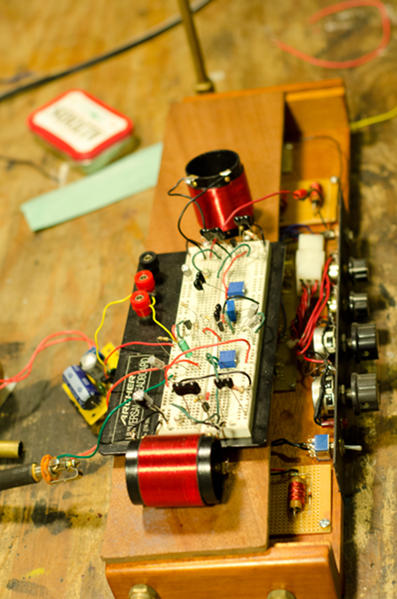
I have just constructed a Lev oscillator -

I used a small EP10 former, on which I wound 2x 120 turns of 0.08mm diameter (aproximately - measured it with a caliper - but its not critical) enamelled (polyurithane) copper wire - into this I inserted a small ferrite suppression bead (Fair-Rite 2673000301)

I actually wound 4 seperate 120 turn coils on this former - I have some ideas about feeding antiphase signals into one to allow electronic tuning, and using the other for output and oscillator coupling.. but for now am just using 2 of the coils.

The suppression bead raises the AL to 10.7, each winding gives about 158uH (at 200kHz), combined inductance is about 620uH

Total wire length is about 5 mtrs - the former costs 35p, the ferrite costs 6p - I recon these assemblies could be manufactured for about £1

Not going to do any extensive testing until ive put a ref oscillator and antenna circuit and mixer together, but it looks like its operating the same as the others - will go into more details soon.

Fred.

Posted: 10/21/2012 5:48:53 PM
Chobbs

From: Brooklyn,NY

Joined: 12/1/2009

"Uncle Howie recommends going with the Melodia VCA. I was ready to dismiss that idea at first, but after some thought, I realized I have a functional version of it under my nose, and it does work pretty good.

Funny- I was just looking at this (again) yesterday- in particular the volume/vca and coils.

Rob- did you build your kustom?  Id be interested in hearing from someone who has made the Melodia/kustom coils from scratch.


Fred- great work! Id like to see your coil- Post some pics if possible. 

Posted: 10/21/2012 6:41:15 PM
DOMINIK

From: germany, kiel

Joined: 5/10/2007

Oops - today i became aware of an error with my breadboarded versionI connected the 1n cap NOT to D/coil BUT to the opposite site of the coil (directly to PLUS). Here comes the update of the waveform at S:

Similar, but different. With the octave range drastically reduced like Fred was expecting and an equalization coil of a much higher value (test with 33mH) being needed (while 3x 4,7mH resulted easily in about 5+ octaves with the "misplaced" cap). At first sight the available waveforms WITH the misplaced cap seem to be more variable..

Fred: Interesting idea to implement four windings.

Charlie: Once i made melodia coils using this once again: Filterspulenbausatz, 7 mm bis 1.8 MHz. 0,1mm wire, same turns like given in that article. It worked well, though i must say that - sometimes - problems with radio reception/noise occured.
Values measured (lowest/highest):
L2: 1-2=not measurable with my equipment, 2-3=80/280uH, 3-4=30/120uH 
L3: 1-2=70/280uH

Posted: 10/22/2012 12:22:06 AM
Chobbs

From: Brooklyn,NY

Joined: 12/1/2009

I finished up the replica coils today and bread-boarded the oscillators and mixer from dominik's/fred's schematic  and patched it into my  EM's antenna circuit.  (4x 10mh and much more needed! )  -    the audio 'out' just going to a little practice amp.

Not really playable  but  for a 1st round  bench test  it sounded surprisingly  well- especially in the low end. harmonically rich w, Lots of 'good' character.  very pleased!   I think that we're on the right track. 

Im using 2n5457's for a fets  and pcb mount 50p trim caps to tune.  fried a mpf102.    12v power supply.     I messed w/ the trims a bit but thought it  sounded best with the mixer gain  highest and the osc pots at their lowest values.      No scope tests yet.

 Subtle trimming of the osc pots and the gain pot does change the tone/sound.     but 1m is way too high for the osc trim pots- should probably be like 10k  or even 1k-

Next- make a melodia( or other?) volume/vca- anyone have some values for the melodia/kustom volume coils?  I can barely read the melodia article, and the parts list and coil info is completely indiscernible. I know the antenna coil is 10mH.

Posted: 10/22/2012 2:30:40 AM
w0ttm

From: Small town Missouri on Rt 66

Joined: 2/27/2011

@ Charlie

My Kustom was factory built in Chanute, Kansas. The friend that gave it to me also blessed me with a ton of electronic scraps including the Kustom coil forms and well over 100 tubes, some of them vintage as in will fit an RCA.

I have no idea what value the coils are. The pitch side runs higher than a Melodia, I think around 230 khz. I don't remember the volume side frequency, I think it was above 400 khz.

It's a pain to get out of the case, but I'm going to open it up next week and do some probing and post what I find.

A higher resolution Melodia article.

A Transistorized Theremin

Congrats on having the very first TW theremin to actually play!

@ Fred

I like (a lot) your volume oscillator method. I was going to use a separate oscillator to reduce the size of the antenna inductor. I never thought of multiplying the reference. 

Brilliant.


Stay tuned.....


Posted: 10/22/2012 3:01:40 PM
FredM

From: Eastleigh, Hampshire, U.K. ................................... Fred Mundell. ................................... Electronics Engineer. (Primarily Analogue) .. CV Synths 1974-1980 .. Theremin developer 2007 to present .. soon to be Developing / Trading as WaveCrafter.com . ...................................

Joined: 12/7/2007

"I like (a lot) your volume oscillator method. " - w0ttm

This method has some far-reaching implications - implications which led me down a quite different theremin route to the conventional.

The first implication is that the reference must be a fixed frequency - it cannot be used for pitch or volume tuning. For me, this is fine - Tuning the antenna or the antenna resonant circuit is, I believe, the optimum place to obtain best linearity on both pitch and volume..

The (initial) tuning procedure is to tune the variable oscillator and antenna for optimum linearity, then tune the reference oscillator for null at the correct hand distance, do final tweeking of the variable components, then never touch the reference oscillator again.

one then needs to tune the volume antenna circuit - I used a 42IF106 to trim the inductance (pins 1 to 3 in series with pins 4 to 6 gives about 950uH with the slug in the centre, down to about 500uH and up to about 1.2mH at extremes) - place this IFT closest to the oscillator / PLL, in series with the fixed antenna inductors.

The major problem with the above is that there is no simple user tuning control for either pitch or volume - One needs to "tune" the volume by making use of the converted antenna -> voltage, and altering this voltages amplification and/or biasing.. This means that you cannot tune too close to resonance, otherwise in some circumstances the volume behaviour will be erratic - "Tuning" by adjusting DC gain / offset does mean that linearity changes marginally if the background / environmental situation changes - its like the usual method of tuning pitch by altering the reference oscillator frequency - the linearity changes slightly every time you tune your theremin in an altered environment.

Pitch tuning cannot be facilitated by adjusting anything except the antenna or inductance of the antenna circuit- one could put a small variable capacitance on the antenna (as discussed before) or alter the antenna area (length) - And for a low cost stable theremin, my screw adjustable antenna works beautifully..

I have developed an electronic means of altering the antenna inductance, but this is way too complex for the TW theremin.

The important thing to remember though is that by switching to my reference oscillator = volume oscillator topology, you do need to alter your thinking about the whole theremin tuning topology - you cannot just take a theremin and modify it by using the reference for volume.

Fred.

Perhaps what I am saying above is that this method, whilst I believe it is far superior, may not be well suited to the TW theremin.


Posted: 10/24/2012 1:38:09 AM
Chobbs

From: Brooklyn,NY

Joined: 12/1/2009

"I wonder how it would perform with a Termen oscillator on the volume side?"

"I think it will work better than the conventional parallel LC oscillators for the same reason that the pitch linearity is better, and that it will be more stable."


Sheesh!    just had 3 paragraphs written and accidentally hit 'refresh"-  all lost  errr. anyway... to sum it up...

..I'd be interested in seeing some ideas for a transistorized lev oscillator/RCA volume circuits,  if any of you talented engineers- so handy w/ the circuit sketch software, feel inclined.


Posted: 10/24/2012 4:23:26 PM
FredM

From: Eastleigh, Hampshire, U.K. ................................... Fred Mundell. ................................... Electronics Engineer. (Primarily Analogue) .. CV Synths 1974-1980 .. Theremin developer 2007 to present .. soon to be Developing / Trading as WaveCrafter.com . ...................................

Joined: 12/7/2007

"..I'd be interested in seeing some ideas for a transistorized lev oscillator/RCA volume circuits,  if any of you talented engineers- so handy w/ the circuit sketch software, feel inclined." - Chobbs

I am not going to contribute any schematics on this subject - I only post stuff I am reasonably certain off, from expierience with actual circuits (except for theoretical explorations, like the Lev oscillator), and I dont have much expierience with VFO based volume circuits.

The only VFO based volume circuits I do have reasonable expierience with is the EPE-2008 theremin, and this works quite well. See: EPE2008_ANOT2.PDF which is the schematic I have annotated with component references.

I would suggest simply replacing the volume oscillator (C20,T3,C21,R25,Q5,VR!,R26,C23) with a Lev oscillator, and putting a capacitor across T4 (pins 1 to 3) to lower the resonant frequency of this filter.

Some means of tuning the Lev oscillator is required if the EPE-2008 volume adjustment scheme is to be duplicated - But I would advise against duplicating it, and instead adding a antenna equalising resonant circuit and tuning this.. Or having no user adjustment of the oscillator frequency, and instead messing about with the gain and/or biasing of the DC amplifier and level shifting op-amp..

As long as the voltage at TP 3 varies proportional to hand position in every environment, one can amplify and shift this voltage to produce a current which controls the volume.. By increasing/decreasing the gain and shifting the offset, one can make the response as snappy or gentle as one wants (well - not true.. You can change the distance over which hand movement affects the volume {gain}, and the position at which it nulls {offset/bias}  but you cannot alter the law/linearity)

I suppose what I think may be worth extracting from the EPE-2008 is the simple filter composed of T4, Q6,R30,C25,R29,C24,R27,R28 and C22.. I used an 42IF106 IF transformer with external capacitor across pins 1-3 for T4, and the following circuits (particularly the opto-coupled VCA) work well.. I think it should be possible to implement electronic tuning on the LEV oscillator by biasing the Fet in a similar way to how the EPE oscillator is tuned (perhaps placing a variable resistor on the fets Source rather than to its Drain, and therebye changing its biasing and concequentially its gate capacitance) but I am extremely cautious about such methods, as they tend to have problems with thermal drift etc, unless the design is implemented by someone who completely understands the circuit - I personally dont think I understand the Lev oscillator well enough, and am not great on fets, so cannot advise.

If winding your own coils for the Lev oscillator, adding an extra winding would allow the EPE design to be duplicated more simply, as this could feed Q6 directly as pin 6 of T3 does.. anly a few turns are required (about 20 to 50uH)

Fred.

Posted: 10/24/2012 4:32:03 PM
dewster

From: Northern NJ, USA

Joined: 2/17/2012

So, bottom line, is there any magic in the Lev oscillator?  I just see it as a split coil design, done more for active component (tube) biasing reasons than anything else, but maybe I'm missing something critical.

You must be logged in to post a reply. Please log in or register for a new account.