Theremin Circuits Scratchpad

Posted: 10/3/2012 10:12:02 AM
FredM

From: Eastleigh, Hampshire, U.K. ................................... Fred Mundell. ................................... Electronics Engineer. (Primarily Analogue) .. CV Synths 1974-1980 .. Theremin developer 2007 to present .. soon to be Developing / Trading as WaveCrafter.com . ...................................

Joined: 12/7/2007

Latest:

THIS IS THE WORKING LEV OSCILLATOR WITH THE CORRECT COMPONENT VALUES! - except for the antenna EQ values which were taken from notes others have made, and are probably completely wrong!


I have also started to analyse the tank circuit independently using simulators frequency analysis function, and will move on then to simulating antenna circuit frequency response, tuning the two seperate section as per RCA instructions, and then connecting them to see what happens..

So far, it looks really exciting - the tank circuit IS a series circuit and it looks like the bottom inductor may be interacting with the antenna in an unexpected way - at present, simulating top and bottom inductors with tuning capacitors connecting these in series gives the right frequencies but some extremely interesting plots!

WARNING! - THIS IS ONLY A SIMULATION!

I am worried about the actual signal levels, particularly on the FET - A real FET might die if subjected to these levels! - more attenuation or some form of clamping is required. (actually, had just seen this after posting - and got a bitb panicked cause I thought id checked - in fact, I had - I was looking at the drain signals and momantarily thought they were gat signals - stupid - I have been up the last 30 hours or so, doing this and work I need to complete this week.. time to go crash..) 

Posted: 10/4/2012 2:20:58 AM
FredM

From: Eastleigh, Hampshire, U.K. ................................... Fred Mundell. ................................... Electronics Engineer. (Primarily Analogue) .. CV Synths 1974-1980 .. Theremin developer 2007 to present .. soon to be Developing / Trading as WaveCrafter.com . ...................................

Joined: 12/7/2007

Rob (w0ttm).. I think you were right!

I don’t think this is an Armstrong oscillator - It may have originated from a Meissner / Armstrong oscillator..

But it has been changed so hugely now that I think it could fairly be called a Lev (Or Termen) Oscillator.

Major difference I can see is that the "tickler" winding has a much greater role in this oscillator, forming 1/2 of the inductance of a Series tank coil.

Fred.

Posted: 10/4/2012 4:36:23 AM
w0ttm

From: Small town Missouri on Rt 66

Joined: 2/27/2011

DOUBLE DAD GUM!!!

I thought I had some MPF 102 fet's. They were MPSA 42 hv bipolars. Blame it on old eyeballs.

An emergency run to Radio Shack and they were out of them.

I'll try a different Shack tomorrow.

Bummer....Rob.

Posted: 10/4/2012 8:15:35 AM
FredM

From: Eastleigh, Hampshire, U.K. ................................... Fred Mundell. ................................... Electronics Engineer. (Primarily Analogue) .. CV Synths 1974-1980 .. Theremin developer 2007 to present .. soon to be Developing / Trading as WaveCrafter.com . ...................................

Joined: 12/7/2007

I have moved discussion of the theoretical aspects related to the RCA theremin to a new thread in the new forum (Thanks Jason!)

RCA THEREMIN in the "Technical Theory" Forum

Posted: 10/4/2012 3:13:40 PM
Chobbs

From: Brooklyn,NY

Joined: 12/1/2009


Guys, - great work- this is awesome and exciting.   - so glad that I saved that Levnet email (howie's) in my inbox for a over year... I knew it was something special!

     So you think mpf102's will work?   I also my try to put together a model termen (oscill)-ator.   BTW - Radioshack also has #26 magnet wire- though it comes in a 3-pack with two other gauges.  the green spool is the 26.   There is just enough wire on the  spool to wind one pitch osc coil (both layers)

Question-  If this goal is to make a full solid state  replica of the RCA, are we still talking big antenna coils and inter-stage audio tx's?  
(this may be getting too far ahead, but...)  also the Volume Circuit?   Performance-wise it is pretty sluggish, but that may be mostly a result of the 120 tube.  I have also always been curious about the interaction (if any) between the 2 windings on the (lg) volume antenna coil.   Should this be considered a TX?  or is it just two separate windings that share a coil form for convenience?  (I  suspect the former, but what do I know?)

Posted: 10/4/2012 3:36:36 PM
FredM

From: Eastleigh, Hampshire, U.K. ................................... Fred Mundell. ................................... Electronics Engineer. (Primarily Analogue) .. CV Synths 1974-1980 .. Theremin developer 2007 to present .. soon to be Developing / Trading as WaveCrafter.com . ...................................

Joined: 12/7/2007

"Question-  If the goal is to make a full solid state  replica of the RCA, are we still talking big antenna coils and inter-stage audio tx's"..

IMO, the goal should be to make a REAL solid state replica - as in, something which sounds and behaves as closely to the RCA as is achievable with easily available components.

Audio transformers are a potential problem - the transformers will colour the sound, and obtaining 'sound alike' parts - probably impossible.

What we really need to get a true clone, is to have a competent engineer with access to an RCA, and for signals on the plate of the mixer, the grid of the preamplifier, and the grid of the power amplifier, to be accurately recorded over the whole pitch range - We also need the volume changed as each of these signals are recorded, so as to be able to determine the harmonic variations (if any) resuting from pitch and volume variations, and by comparing signals at these different test points, determine the audio transformers charactaristics and 'coloration' attributes.

But obtaining the above data is most unlikely.

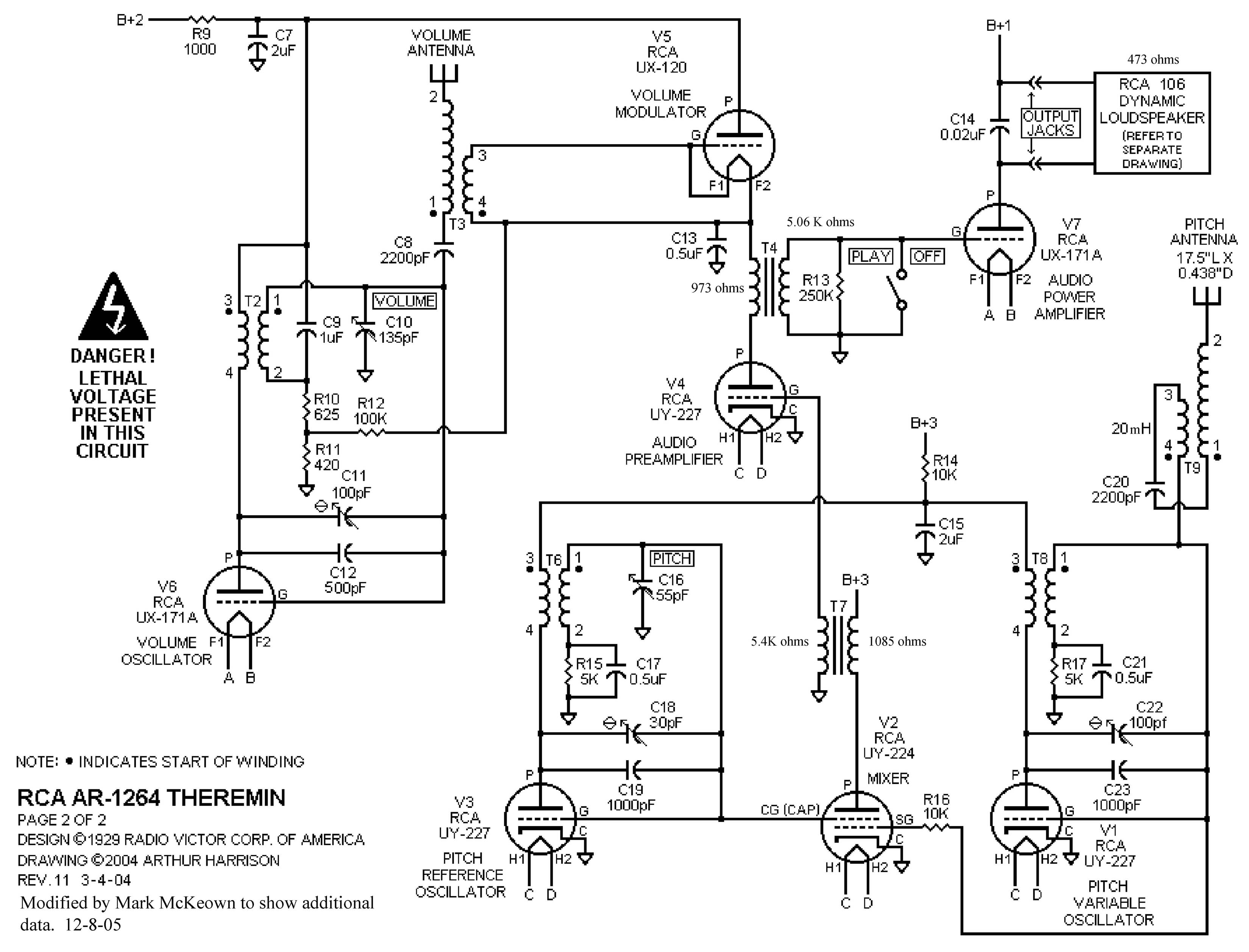
We know that there must be a roll-off quite a way down below 172kHz, caused by the tubes and / or transformers, as there is no actual filter in the circuit to remove thye HF components from the mixer - I suspect T7 alone removes the bulk, if not all of the HF..

I am inclined to think that most of the tonal charactaristics will be determined by the mixer and its input waveforms.. And I am inclined to think that, if we get this section right, we can tailor the harmonics using non inductive mechanisms - as in, standard filters or perhaps a more complex graphic or parametric equaliser circuit.

The volume circuit (as in, the antenna / detector) seems to me, at this time, to be non-critical.. But I am not going to assume anything, and will analyse this - However, at the present time I think that this does not need to tightly follow the original design.. I am happy to evaluate the existing design, but I cannot participate in the design of a solid state replacement.

I think that a H11F1 opto isolated FET would probably be the ideal VCA, having wonderful 'tube-like' qualities.

We probably cannot get samples from inside the RCA - But at least we need samples of the RCA output signals, so that we can compare our output against these - Once the mixer has been built, there will be the (probably long) job of fine tuning the amplitudes of the signals going into the mixer, possibly tweeking the oscillators, and then possibly developing complex post-mixer equalisation - and all this will need to be done while actually listening to RCA samples and comparing these, both by ear and with spectrum analysis, against what the clone is producing..

It aint over until the tiny fat lady really sings!

Fred.

"  I have also always been curious about the interaction (if any) between the 2 windings on the (lg) volume antenna coil.   "

I havent studied this section yet - it looks even wierder than the pitch oscillator did before I understood it - but it is a similar configuration, except there are both series and parrallel components .. No, I dont yet understand it, sorry - T3 3-4 looks like some sort of rectification / integration using C13 - but I dont understand why C13 doesnt add so much capacitance through T3 to the antenna, that the antenna becomes useless - Nope - That circuit aint clicking.. needs perhaps an hour or even a simulation (wish I had a good triode model..)

Posted: 10/4/2012 3:56:43 PM
Chobbs

From: Brooklyn,NY

Joined: 12/1/2009

Fred,

    I have a working (and pretty sweet sounding, if I may say so) rca-replica right here next to me(as seen in my updated profile pic) and a scope freq counter, mutlimeter, etc.  Consider them at your disposal.     Unfortunately  the only thing i dont have is the knowledge....   If you can explain the what, where, and how to do the testing- Ill try my best to get you any info/samples you may need.  (Also no function/signal generator so I cant really do resonance.)

My replica is built on a Radiola 60 chassis, use the same power supply and has a pair of original GW-24 interstage tx's - all connected to an original RCA 106 loudspeaker-   I think this could be a satisfactory control subject.

BTW-  A suitable replacement audio tx is available at Antique Electronic Supply-p-t156, I belive. From what I read, other builder report little or no difference in the sound between  replica's built with them vs the original GW-24.


Posted: 10/4/2012 4:24:57 PM
FredM

From: Eastleigh, Hampshire, U.K. ................................... Fred Mundell. ................................... Electronics Engineer. (Primarily Analogue) .. CV Synths 1974-1980 .. Theremin developer 2007 to present .. soon to be Developing / Trading as WaveCrafter.com . ...................................

Joined: 12/7/2007

"I have a working (and pretty sweet sounding, if I may say so) rca-replica right here next to me, and a scope freq counter, mutlimeter, etc.  Consider them at your disposal.     Unfortunately  the only thing i dont have is the knowledge....   If you can explain the what, where, and how to do the testing- Ill try my best to get you any info/samples you may need.  (Also no function/signal generator so I cant really do resonance.)" - Chobbs

WOW! -

It should be quite straightforward.. Hold it.. Dont follow the following instructions until I have checked the loading effects - you may need an active probe :-(

first, you need to construct a probe ( one with a clip ) having a good high voltage capacitor connected to it - in fact, two series capacitors just to be safe.. Then a resistor in series with these, say 10k, and say each capacitor about 22uF non polarized - and a 10k pot which you set low and then crank up..

Probe---22uF 300V---22uF 300V --- 10K----- 10k Potentiometer --- Ground

Wiper of potentiometer to your recorder input..

Best to use screened cable, but only connect the ground at the output end.. run a seperate ground lead between your recorder and the RCA.

If you need, I will mark up the test points on a schematic - If you have a schematic you are familiar with, email it to me and I will do this.. If you have a layout diagram, email this and I will mark up the test points.

Samples from the innards! - Now thats something I never thought id hear!... Life is really full of surprises! ;-)

Thanks!

Posted: 10/4/2012 4:34:22 PM
FredM

From: Eastleigh, Hampshire, U.K. ................................... Fred Mundell. ................................... Electronics Engineer. (Primarily Analogue) .. CV Synths 1974-1980 .. Theremin developer 2007 to present .. soon to be Developing / Trading as WaveCrafter.com . ...................................

Joined: 12/7/2007

Is your 'scope capable of connecting to a PC (usb interface or whatever)? If it is, and if you can record the data in some standard format (XLS or WAV or whatever) then you wont need a probe if your scope / probes can handle the DC voltages and (as almost every scope I have seen) has AC coupling option.

Posted: 10/4/2012 4:45:51 PM
Chobbs

From: Brooklyn,NY

Joined: 12/1/2009

You can either go with the Wiring Diagram(p.16)  in the RCA service manual, or  Art Harrison's schematic. both  are pretty clear  and easy to read.   ( Boy, the original RCA schematic is terrible, one of the most confusing schematics Ive ever seen....the wiring diagrams, on the other hand, are phenomenal- works of art! )  

Ill see what i can pull together for the probe... the 22uf,non-polarized may be a little tough to obtain w/o ordering from a distributor. 

You must be logged in to post a reply. Please log in or register for a new account.