Problems with volume circuit

Posted: 2/18/2013 9:07:49 PM
mupplet

Joined: 2/4/2013

Hi! Just finished building my theremin according to this schematic:

http://www.thereminworld.com/pics/schematics/AnotherThereminCircuit.jpg

Pitch-wise, the theremin works great and I can tune it to sound and play like any other theremin, but I'm having problems with the volume part of this build. The volume antenna actually changes the pitch as well as the pitch antenna does. I'm not an expert in electronics, but this is how I believe this schematic should work; the capacitance of the hand in proximity to the volume antenna causes the frequency to lower from 15 MHz to the reference volume oscillator at 10 MHz, thereby causing it to short-circuit somehow and lower the voltage controlling the amplifier. Well, it's not working for me...

The frequency of the pitch oscillators (with my larger-value coils) is 700-800 kHz, which should keep them from interfering with each other (?).

Worth to mention is the fact that connecting the center coil-tap to L2 causes the theremin to stop sounding at all. I keep it disconnected for that reason.

Another thing that could make a difference is that I replaced the BAT54 (D1) diode with a BAT43, since the BAT54-diode was too darn small to solder (SOT-23). Is it a legit replacement, or is it causing me the problem?

Really grateful for help!


/Philip

Posted: 2/18/2013 11:31:07 PM
FredM

From: Eastleigh, Hampshire, U.K. ................................... Fred Mundell. ................................... Electronics Engineer. (Primarily Analogue) .. CV Synths 1974-1980 .. Theremin developer 2007 to present .. soon to be Developing / Trading as WaveCrafter.com . ...................................

Joined: 12/7/2007

Hi Philip

This is one of the most horribly drawn schematics I have ever seen! - I rarely find a schematic where it is difficult to determine the operation quickly, but this one will probably need to be re-drawn to make it comprehensible!

The area where I am most puzzled is (what looks like) a linkage between the pitch and volume sections via R4 and D1.. I might just be a bit slow today, but this makes no sense to me.

If nobody else gets back on this, I MAY re-draw the schematic and run it through the simulator if I have time.. But it may be a week before I get back, if I do.. so I hope someone else gets back to you first.

As for the BAT54/43, the BAT54 has a slightly higher capacitance, but I doubt that this is significant.. However, right now I do not know what the function of that diode is .. it must be forward biased or Q2 would serve no function..

Nah - dont know! ;-)

I am curious though - I have never understood what attracts people (particularly those who are not confident about their electronic knowledge / skills) to pick the most obscure theremin circuits they can find - ones with no history or good documentation - and attempt to build them !

Really, when you do this, you are on your own..  If you pick some standard circuit like the EM or SC, there are lots of others who have trod those paths and can offer advice - But with a circuit like you have picked, which has the added complication of running at absurdly high frequencies, its only certified lunatics like me who MIGHT spend the required time to look at yout (technical) problem, LOL ;-)

I personally think that a "sort out" is long overdue on TW's technical pages - We at least need a document detailing the schematics etc in the library, and "rating" these by technical merit / difficulty / popularity etc...

Fred.

Posted: 2/19/2013 1:17:56 AM
FredM

From: Eastleigh, Hampshire, U.K. ................................... Fred Mundell. ................................... Electronics Engineer. (Primarily Analogue) .. CV Synths 1974-1980 .. Theremin developer 2007 to present .. soon to be Developing / Trading as WaveCrafter.com . ...................................

Joined: 12/7/2007

Ok - I see it!

Most peculiar topology! ... And, to be honest, I dont like it at all!

Unlike most theremins where the reference and variable frequencies are mixed, anf the difference (audio) frequency is taken to a VCA which is controlled by the volume circuit, this one changes the level of the VFO output only, before mixing.

The volume oscillator drives a filter (L3,C22,C8) via Q5 - the -ve 1/2 cycles are rectified by D1 and produce a -ve voltage on C4, this voltage controls the conduction of Q2 which (hopefully) controls the amplitude of the variable oscillator signal at Q1e... Ugh!

I cannot see how the changing loading on Q1e could do anything but change the frequency of the VFO!

Anyway, the idea was obviously that by controlling the amplitude of the VFO, the resultant difference amplitude (due to mixing at Q3 base) would be controlled.

Not worth building, not even worth simulating.. The best you can do is to  connect R4 to GND (as in, duplicate the reference oscillator), and disconnect it from C4.. Then check on C4 to see if the voltage varies as the pitch antenna is used.. If it does, you have a pitch-only theremin and a voltage-outputting volume antenna..

You will need to build some VCA which takes the voltage from C4 to control the level, and insert this VCA in the audio path somewhere - perhaps between C14 and R16.

IMO THIS IS A RUBBISH DESIGN AND IMO SHOULD NOT BE IN THE TW TECHNICAL LIBRARY WITHOUT APPROPRIATE WARNING!

Fred.

Sorry - I forgot to mention that you need to remove Q2 and wire-link the C and E points.. and you will probably need to modify the filter / rectifier circuit dependent on what VCA circuit you use...

If you really want the original idea, you need to add a buffer stage between Q1E and Q2C.. another 2N222 with its base conected to Q1E (which is now pulled to ground via a 3k3) its C connected to VCC, and its E connected to the collector of Q2.. No guarantees, but this should at least remove some of the pitch/volume interaction.. I will paste modified schematic here in a moment..

Posted: 2/19/2013 2:00:19 AM
FredM

From: Eastleigh, Hampshire, U.K. ................................... Fred Mundell. ................................... Electronics Engineer. (Primarily Analogue) .. CV Synths 1974-1980 .. Theremin developer 2007 to present .. soon to be Developing / Trading as WaveCrafter.com . ...................................

Joined: 12/7/2007

ABSOLUTELY NO WARRANTY THAT THIS WILL WORK!

Add the components marked in yellow, its still horrible, but the VFO should be less subject to volume influence I think.


I have spent a fair time looking at this for you, please could you spend a few minutes and do something for me?

Just have a look at this site! ;-)  http://streetkidsrescue.org/

Fred.

PS - BEST TO PUT A 3k3 RESISTOR BETWEEN THE BASE OF THE NEW TRANSISTOR (the one marked in yellow) AND THE EMMITTER OF Q1

Posted: 2/19/2013 2:49:10 AM
FredM

From: Eastleigh, Hampshire, U.K. ................................... Fred Mundell. ................................... Electronics Engineer. (Primarily Analogue) .. CV Synths 1974-1980 .. Theremin developer 2007 to present .. soon to be Developing / Trading as WaveCrafter.com . ...................................

Joined: 12/7/2007

Oh, one other thing I just noticed ;-) LOL..

"Worth to mention is the fact that connecting the center coil-tap to L2 causes the theremin to stop sounding at all. I keep it disconnected for that reason."

You have a problem there which needs sorting out..

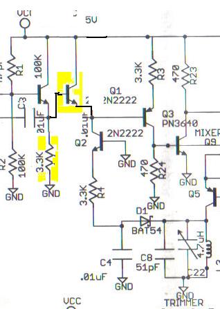
L2 C5 forms an oscillator with Q4.. without the tap, there is no feedback path, and I cannot see how this oscillator can run..... Except for the fact that the frequency is so absurdly high anything is possible! ;-)

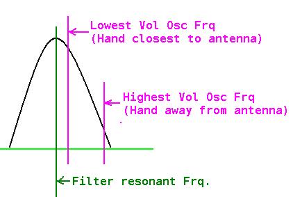
There is only one volume oscillator, no volume "reference" oscillator - the circuit of Q5 L3 C8 and C22 form a filter - this filter will be tuned to provide maximum amplitude at (i think) the highest frequency, and the amplitude will drop as the volume oscillator frequency drops.. But you need the volume oscillator to be running correctly to drive the filter.. and without the tap on L2 connecting via C7, I cannot see that it will run correctly, if at all!

There is absolutely no "crafting" in this design - the component values are absurd, C7 for example.. 10nF @15MHz ?? You could probably use a 10pF there quite happily! - the same is true for other capacitors - someone had a box of 10n's they wanted to use up! ;-)

It reminds me of a radio engineer I worked with in my youth - Whenever there was an unknown capacitor, he would tell me to "stick a .1 in" LOL ;-) .. in most cases it worked! But occasionally there was a puff of smoke from some "unrelated" component!

IMO, its really not worth spending too much time on this circuit unless you are doing so for educational / exporation reasons - and its one of those circuits which will teach you nothing about good electronics practice.

Forget about the sound - get the volume circuit working so that uou can see a change in voltage on C4.. perhaps even disconect C2 and C10 to disable these oscillators while you do that.. this removes possible causes of confusion.

Once you have the volume voltage showing, then re-enable the oscillators.


I really do want to understand why you chose this circuit!  There are no details regarding the inductors for example - How did you determine where to put the taps or what to wind them on ? .. They are tunable inductors - Even I wouldnt venture to obtain formers and wind these coils unless I had extremely good reason to do so - And I wouldnt have any idea where to obtain ready built parts!

This circuit is more complex than the EM theremin designed by Bob Moog - The EM would be easier to build, components would be easier to find, and you would end up with a good playable instrument..

In order to have got the circuit to operate to the degree you did means that you must have sourced or wound your own inductors - You must therefore have quite a high degree of electronics competence..

And I just dont understand it!  Why did you pick this awful circuit ??? I really am not trying to pick a fight or give you an earbashing - I am trying to understand... You see, I believe nobody does anything without believing their choice is a good one - So perhaps I am wrong, perhaps there was good reason which I cannot see.

Fred.

Posted: 2/19/2013 5:07:14 PM
mupplet

Joined: 2/4/2013

Hello there! I can't tell you how much I appreciate the fact that you are bothering to help me although I have gone down the wrong path! I will surely check your website out and donate a few bucks, it's the least I can do! :)

Before we get into the electronics, I'm going to try to explain why I chose this circuit, although I'm not entirely sure myself. Eager to start this build I browsed through schematics trying to find one that seemed appropriate. Although it turned out not to be, the circiut seemed simple. What I think appealed to me was the fact the pitch-part is very simplistic on this schematic. Around the pitch antenna there's basically a "two-component" LC-circuit with an antenna attached to it. Looking at other theremin schematics now, I see what you're saying, and I would have chosen another one any day of the week! Unfortunately, I don't have the time, and this build is after all educational.

I have to say it's a comfort to understand that this theremin isn't working like other theremins, because I never got my head around the volume circuit and reading about how it's supposed to work just got me even more confused.

The inductor matter troubled me as well, but then I understood about their feedback purpose, and I wound the coils as the schematics was showing me (a bit of a shot i the dark, I must admit) where the taps on L1 and L4 are placed a 1/4 in from one side. I started winding the coils, and at halfway I started twisting loops and carving away the laquer of the coil every 10 or so turn. Then I use crocodile clips to be able to tune it. I used 0.3mm copper wire wound around a 40mm cardboard tube (read educational build ;) ).

I will try the methods you have suggested, and thanks again for all your help! As I mentioned, I will visit your website and tell some friends to do so too. Thanks!


Philip


Posted: 2/19/2013 9:28:18 PM
mupplet

Joined: 2/4/2013

Here's me again! Disconnected the pitch- from the volume circuit and removed Q2 and wired e and C together as you suggested. This question might sound really stupid, but I'm on really thin ice with this volume circuit; when you say that I should check the voltage on C4, do you mean placing the other probe of the voltmeter on the Vcc terminal by the volume oscillator?

Philip

Posted: 2/20/2013 4:02:54 AM
FredM

From: Eastleigh, Hampshire, U.K. ................................... Fred Mundell. ................................... Electronics Engineer. (Primarily Analogue) .. CV Synths 1974-1980 .. Theremin developer 2007 to present .. soon to be Developing / Trading as WaveCrafter.com . ...................................

Joined: 12/7/2007

"This question might sound really stupid, but I'm on really thin ice with this volume circuit; when you say that I should check the voltage on C4, do you mean placing the other probe of the voltmeter on the Vcc terminal by the volume oscillator?" - Philip

No, what I mean is check the voltage across C4 - as in, one probe to GND, the other to C4 / D1 (anode).

You should see a voltage here which goes between GND and some -ve voltage below ground, and this voltage (if the volume oscillator and stuff are working correctly) should vary as the hand approaches the volume antenna.

Adjustment of the trimmer (C22) should tune this circuit - it will need to be tuned so that as the hand approaches the volume antenna, the voltage goes more -ve.. There are two tunings which will influence this, one is C5 which will alter the volume oscillator frequency, the other is C22 which will tune the filter.


You need to tune the filter and volume oscillator so that the filters resonance is just below the lowest frequency the volume oscillator ever runs at if you want the circuit to behave in the normal way with volume increasing as hand gets more distant...

Alas, this design even gets these fundamentals wrong - because one actually wants the curve to be sharper as the hand moves away, to give a log response - so one wants to work with the other half of the resonant curve (as in, tune the filter so it is just above the highest vol oscillator frequency).. But if you did that (and I think for this design that would be best) you will get louder volume as the hand gets closer to the volume antenna.

Exactly where you tune the oscillator / filter will be experimental - there will be a trade-off between how "silent" the theremin becomes, and how dynamic the response will be..

You may find that inserting a 100k resistor between the probe and the test point will be a good idea - you dont need accurate readings, so this resistor will reduce loading effects.

Thanks for sharing the reasons for your choice. Once again (TW STAFF - PLEASE NOTE!) I feel it would be far better if there was some general documentation warning people of pitfalls with certain designs, or if "designs" like this one (and the Glasgow "theremin") were removed from the library..

I accept the reason for keeping these - but doing so without warning people is, I feel, irresponsible.

Fred.

Posted: 2/20/2013 4:33:01 AM
FredM

From: Eastleigh, Hampshire, U.K. ................................... Fred Mundell. ................................... Electronics Engineer. (Primarily Analogue) .. CV Synths 1974-1980 .. Theremin developer 2007 to present .. soon to be Developing / Trading as WaveCrafter.com . ...................................

Joined: 12/7/2007

"I have to say it's a comfort to understand that this theremin isn't working like other theremins, because I never got my head around the volume circuit and reading about how it's supposed to work just got me even more confused." - Philip

Do you have any other documentation on this circuit? - All I have been able to find is the schematic you linked to - If there is anything else, please could you link to that?

Fred.

Posted: 2/20/2013 3:41:45 PM
mupplet

Joined: 2/4/2013

Hi there Fred!

Did some voltage testing across C4 and it is indeed changing when approaching the antenna, but it maxes out around -17 millivolts, would that be enough to use with a VCA?

If so, do you have any schematics or advices for building a VCA?

Unfortunately, I do not have any more documentation on this particular schematic. I'm also starting to wonder why I chose this schematic when thinking about my last sentence ;)

Philip

You must be logged in to post a reply. Please log in or register for a new account.