My New Year gift to TW: A new theremin circuit

Posted: 12/28/2013 11:46:46 AM
Thierry

From: Colmar, France

Joined: 12/31/2007

While many new theoretical discussions continue showing up here on TW, it's been a long time that a new theremin design which works in practice and can easily be built has been published in these forums.

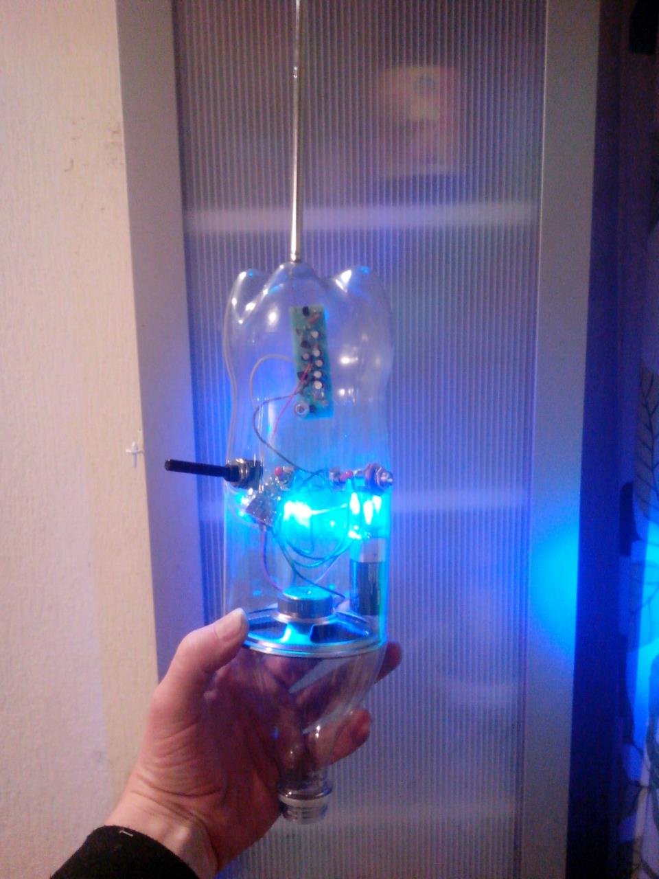
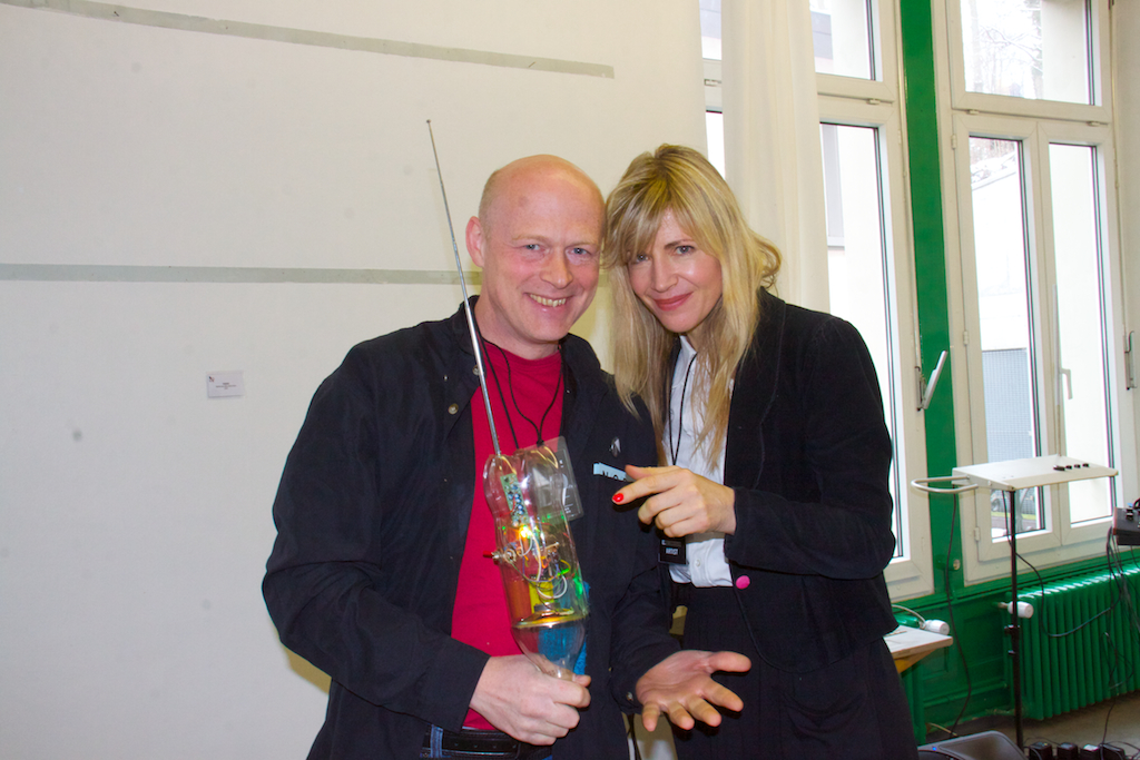
That's why I decided now to publish the following circuit. It's another simple pitch-only theremin design which I have developed over the last 3 years, first as a response to the numerous demands which I got from High school students for their projects. Later, the Dutch thereminist Wilco Botermans and me started using this circuit during DIY-workshops for beginners which we organized in many European countries. Finally it was also used by Wilco for an installation with 5 of these theremins, installed in Coke bottles, in a setup which allowed the public to move within the common field, producing polytonal sounds.

Wilco's wife Jessica gave this circuit its name "Thierrymin", because it is very small and because she wanted to honor its inventor...

Principle of Operation:

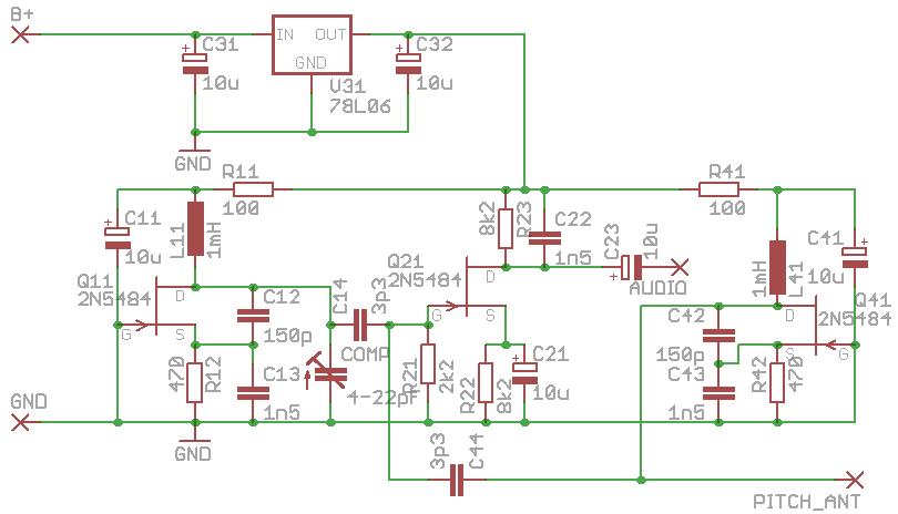
There are two identical oscillators around J11 and J41 working around 410kHz. One will be connected to the pitch antenna (see below), the other has a small variable capacitor which allows to adjust its frequency and thus do the coarse pitch tuning. While the 2N5484 FET transistors are now out of production, they can still be found almost everywhere, but any other N-JFET with a pinch-off voltage of 1.5V will do. The oscillators work in a grounded gate configuration which provides best independence of the internal junction capacitances. That makes them fairly stable in this simple circuit. The inductances L11 and L41 are simple 1mH fixed inductors which are not critical, as long as their self resonant frequency is above 800kHz. R11/C11 and R41/C41 decouple both oscillators which gives the circuit a nice low audio frequency response, together with the small coupling capacitors C14 and C44.

The mixer around Q21 is works as an active rectifier due to the high source bias resistor R22, so that only the positive halves of the sum signal at the gate will pass through. The advantage compared to a simple diode mixer is a better decoupling between output and input, so that the output load (the connected audio cable and amplifier) will not affect the mixer's response. C22 filters the remaining RF component from the audio output signal.

V31 is a simple 6V voltage regulator which allows the circuit to be operated from either a 9V block battery or any DC power supply between 9 and 12V. As a pitch antenna, a telescopic antenna with a diameter of 6mm (1/4") and a length of 50cm (20") works best. After building the circuit and installing it together with the pitch antenna in whatever non-metallic housing, pull the segments of the telescopic antenna fully out, but not the last (thinnest) one, which should be pulled out only at the half of its length. Now adjust the variable capacitor for a decent pitch field with the zero point at about 50cm (20") from the antenna. That was the coarse pitch tuning. Fine tuning can now be done by pulling out or pushing in the last antenna segment by a few millimeters until you get a pleasant field geometry and tone spacing.

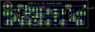
Below you'll find the schematic and a circuit board layout. Everything is with a 0.1" spacing, so that the circuit can also be built on a Veroboard, but it should be one with round copper dots. The classic Veroboard with stripes or square copper dots will give too much parasitic capacitance and thus degrade the circuit's performance.

Have fun building it and don't hesitate to ask your questions here!

Schematic


Posted: 12/28/2013 5:43:18 PM
Thierry

From: Colmar, France

Joined: 12/31/2007

Here a few application examples:

a) Levnet member Arno43 integrated it with a deco-dog:

Wilco Botermans installed it together with a small LM386 based audio amp in a Coke bottle. Dorit Chrysler was amazed, too:


Swiss thereminist and organizer of the NODE festival Coralie Ehinger used it to pep up some brochure stands :

Posted: 12/28/2013 7:55:43 PM
gaudi

From: Switzerland (CH)

Joined: 8/6/2010

Thanks for sharing. I remember the stand at the entrance and was wondering where the circuit came from

Urs

Posted: 12/28/2013 8:18:33 PM
Thierry

From: Colmar, France

Joined: 12/31/2007

Hi Urs, you are welcome. If I'm well informed, we well meet in about 4 weeks in Lausanne. This could be an occasion to have some beer together and to discuss...

Posted: 12/28/2013 11:25:33 PM
FredM

From: Eastleigh, Hampshire, U.K. ................................... Fred Mundell. ................................... Electronics Engineer. (Primarily Analogue) .. CV Synths 1974-1980 .. Theremin developer 2007 to present .. soon to be Developing / Trading as WaveCrafter.com . ...................................

Joined: 12/7/2007


Hi Thierry,

Quite an interesting approach - not one I would have selected, but it seemst to work..

A couple of issues "worry" me a bit - First is the DC current through the inductor - this could be a few mA easily, so selection of the inductor may not just be " simple 1mH fixed inductors which are not critical, as long as their self resonant frequency is above 800kHz " - the ferrite core of the inductor and its BH as well as thermal charactaristics could / will affect performance.

Then I am not sure about its start-up performance, particularly with the R11/C11 R41/C41 'slugging' effect - Not having played with this oscillator ever, at all, what I say is pure first gut feeling - but I would imagine that start-up would be better secured by a fast +V transient at the top of the inductor than from a slugged supply (oh, I do understand why you need to do this to isolate supplies - and I may be completely wrong about my analysis) .

Going back to the DC current - It may well be possible to use this for tuning, by making R12 somewhat variable - say a 500R variable resistor in series with R12.. But whatever, care must be taken in selection of an oscillators inductor when there is any significant DC current through it.

I wont be adopting this oscillator ;-) .. IMO Dewster's series LC CMOS oscillator guarantees start-up and, and also provides higher antenna voltage, and with series LC there is no DC through the inductor.. And a 74HCU04 or similar is easily obtainable and probably costs less than a 2N5484

Fred.

Posted: 12/28/2013 11:45:20 PM
Thierry

From: Colmar, France

Joined: 12/31/2007

Fred, that's most probably a question of difference between theory and practice. The average DC through the inductors is only about 1.3mA each (measured). Thermal drift is not a problem under these conditions because both inductors will create about the same drift which will finally be eliminated by subtraction in the mixer.

I never saw any startup-problems on the about 60 circuits which have already been built by amateurs during workshops or as school projects and professionals like Wilco or me. The time constant of the R11/C11 network is small enough to allow sufficient self induction in L11 during power up. It was my design decision to keep the DC operation points of the oscillators fixed (and opting for a "mechanical" tuning), because this would eliminate the risk of startup problems and keep the oscillators' amplitudes constant which guarantees a stable output waveform and level.

In ever case, this design is not for you! It's for beginners who want to do a little soldering and have a nice audible and playable result which works for sure and at low cost.

I have also some more complex designs (among others with DC free inductors and higher antenna voltages) in the drawer, but everything depends on the specific requirements... When people ask for a VW, it makes often no sense to try to sell them a Mercedes.

Posted: 12/28/2013 11:51:56 PM
FredM

From: Eastleigh, Hampshire, U.K. ................................... Fred Mundell. ................................... Electronics Engineer. (Primarily Analogue) .. CV Synths 1974-1980 .. Theremin developer 2007 to present .. soon to be Developing / Trading as WaveCrafter.com . ...................................

Joined: 12/7/2007

"In ever case, this design is not for you" - Thierry

You are right on all points, Thierry - Often theory gives "warnings" one can ignore and circuits work fine even if the calculations say they may be prone to problems..  I often wonder if, due to my safety critical design career, I am too pedantic - I just cannot bring myself to ignore any warnings!

And its certainly a simple little circuit! I am a little surprised you opted for JFET's though - I wouldnt let a "beginner" close to such ESD sensitive parts ;-) .. give them safe bipolars !

;-)

Fred.

"When people ask for a VW, it makes often no sense to try to sell them a Mercedes."

Too true! - Particularly if you are stupid enough to give them a Merc at the price of a VW ;-)

Posted: 12/29/2013 12:10:57 AM
Thierry

From: Colmar, France

Joined: 12/31/2007

I prefer working with JFETs because they have certain characteristics which are more similar to the familiar components I grew up with : tubes (or valves as the British say). I know that electrostatic discharge may be a problem, but in this circuit I think being on the safe side because the gate is grounded, the source has a low resistance (470R || 1n5) towards ground and the drain sees about 135p towards ground. I'd worry much more when the inductor was connected in series with the gate...

And... (I know that it's not a mathematical proof) ...there was up to now only one single FET killed in 60 circuits (which makes 180 FETs) in 3 years and that was Wilco, accidentally applying a positive voltage to its source pin, thus driving the gate-source diode into reverse breakdown...

Posted: 12/29/2013 7:32:17 PM
FredM

From: Eastleigh, Hampshire, U.K. ................................... Fred Mundell. ................................... Electronics Engineer. (Primarily Analogue) .. CV Synths 1974-1980 .. Theremin developer 2007 to present .. soon to be Developing / Trading as WaveCrafter.com . ...................................

Joined: 12/7/2007

"was up to now only one single FET killed in 60 circuits (which makes 180 FETs) in 3 years " - Thierry

Not wanting to hijack this thread at all, and for the purposes of a cheap non-critical toy what I say in the following is of no relevance .. But for anything where reliability is of importance, IMO its highly relevant...

The reason for the huge expense manufacturers go to in order to have ESD reduced assembly areas is not primarily because devices "blow up" - its because parts are damaged by ESD in unseen ways - Actual "instant" failure is rare - a sensitive part exposed to a ES discharge is much more likely to fail days, months or years after its damaged - the damage is unseen (if parts simply failed on exposure it wouuld be far cheaper to just locate and correct these on test, rather than all the expense involved with ESD clean rooms etc) - one may perhaps get 1% instant failure on exposed parts - the other 99% are potentially  ticking time bombs.

Actually, the above applies to many parts, even passive components - but the probability of early failure on FETs and the like due to ESD is hugely greater.

Fred.

*Mean Time Between Failures (MTBF) is an essential documentary requirement for any safety critical application, or any application where reliability is required - It is not possible to derive MTBF for any part which MAY have been subjected to ANY condition outside of the components specification - For this reason there are filing cabinets full of specifications and standards on how components must be handeled for such applications, as without these, one could never produce the required documents / certifications - You simply wouldnt have the data to compute failure probabilities.

IMO Its the most horrible boring tedious aspect of design which fortunately has been made simpler through software and manufacturing standards - back  20 years ago even simple safety/reliability critical applications needed perhaps > 30% of the total project time just to sort out this stuff.. And this was just the hardware - any software had its own set of standards and tests etc.. Its probably now the software which is the most likely and least predictable cause of failure.

Posted: 1/4/2014 12:52:34 AM
TheIMUman

Joined: 1/3/2014

If I'm going to build this, the first thing I need to do is understand the schematic.  I haven't built that many circuits, just a few, like a voltage regulator and a battery balancing circuit.  The balancer used a MOSFET, some resisters, capacitor and two LED's.  I mention it only because it was super sensitive to anything within 10 feet and would get out of sync or go into sync.  It was an "antenna" of some sort and could sense my mood even. 

Anyway, my questions are about two of the connections and components.  1n5, is that 1.5 nano farads?  And the audio only has one connection?  Is that a speaker with the + connecting as shown and ground goes to any ground?

I might build this on a breadboard, is that an adequate spacing?

You must be logged in to post a reply. Please log in or register for a new account.