


"Ray B posted a link over on levnet. He spotted that too, and thinks the S may be an F." - GordonC
Good catch! Maybe the TMS320F28069?
"Ray B posted a link over on levnet. He spotted that too, and thinks the S may be an F." - GordonC
Good catch! Maybe the TMS320F28069?
I just sent an email to Linda at Moog Music about the possibility of procuring a Theremini evaluation unit for video demonstration purposes. Make some noise if you think this a good idea. I'm not entirely sure if the Moog Theremini team is reading this thread, but just in case, let's make some grass roots.
It would be most unusual for a company larger than a garden-shed boutique manufacturer to enter into a public dialogue about their products, but I would welcome it and see it as a forward thinking and mutually beneficial move.
There are a bunch of Theremini assembly pix at the Moog site, one of which is the inside view used in that EE Times article:
http://www.moogmusic.com/news/theremini-now-shipping
So much for "Moog Music's Theremini is assembled in the US by a single person..." I count at least 3 guys monkeying around with the guts. Not sure if they're married or not. ;-)
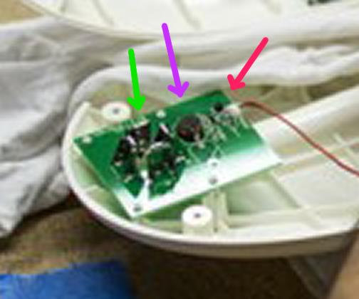
I "enhanced" (cropped and blew up) the view of the pitch board above.
Green arrow points to what I'm certain is the antenna connector, which is four vertical thingies in a square formation.
Purple arrow points to what looks like a ferrite inductor. Note the silkscreened empty space next to it in the foreground, and the extra hole. It looks like they have at least two population options for this inductor.
Red arrow points to what might be a through hole transistor?
The board is quite sparse, I doubt that it is more than just a simple oscillator. if they are doing any analog heterodyning it is happening on the main board, or digitally inside the DSP.
Looks like it is held in position by four plastic posts, which might be kind of shaky / fragile. I wonder if it would survive a drop where the antenna gets a good rogering?

From: Eastleigh, Hampshire, U.K. ................................... Fred Mundell. ................................... Electronics Engineer. (Primarily Analogue) .. CV Synths 1974-1980 .. Theremin developer 2007 to present .. soon to be Developing / Trading as WaveCrafter.com . ...................................
Joined: 12/7/2007
Dewster, - Is that the pitch antenna board? - looks to me like its on the volume side? - but im not sure... also, is that lead to it carrying more than one wire? would need +V and Gnd as well as osc out if it was an oscillator - and if that was a transistor then it kinda goes against what Moog were saying about the front-end being an EW..
No ESD part I can see - but who knows, there may be SMD on the underside - But whatever - if the GND is running || to the antenna (or osc) signal in that wire, then any ESD part would probably be almost useless anyway... But at least they're wearing straps for the photograph session ;-)
Looking at the production line I suspect it may be a world record for the number of theremin (or at least somewhat theremin related) instruments ever produced in one batch..
The TMS320 family has been used quite a lot for monophonic synth applications in the past, I remember some synth developers back >10 years ago employing (or exploring) them - I think some may even have been produced (I seem to remember that Sequential Circuits produced a digital / analogue hybrid poly synth that used the TMS320 as a wave-table oscillator) - I suspect there is/was quite a lot code available.
But anyway - looking at the boards isnt going to answer any questions about this beast - so far, none of the important questions have really been answered, and I suspect that it will only be after thereminists have parted with their money and fully evaluated the instrument we will get any idea about stability, linearity, latency, playability - let alone issues of reliability / robustness etc.
Fred.
"Is that the pitch antenna board? - looks to me like its on the volume side? - but im not sure..." - FredM
The Theremini is reversed, which you can see in the full picture:

"... also, is that lead to it carrying more than one wire? would need +V and Gnd as well as osc out if it was an oscillator - and if that was a transistor then it kinda goes against what Moog were saying about the front-end being an EW.."
I imagine it's a cable of some sort connecting the pitch board to the main board. That looks like a blob of goo affixing the cable to the oscillator board. You're right though, it doesn't look like an EW in terms of the components used.
"No ESD part I can see - but who knows, there may be SMD on the underside - But whatever - if the GND is running || to the antenna (or osc) signal in that wire, then any ESD part would probably be almost useless anyway... But at least they're wearing straps for the photograph session ;-)"
Good point, I wasn't thinking about that cabling in terms of ESD.
"Looking at the production line I suspect it may be a world record for the number of theremin (or at least somewhat theremin related) instruments ever produced in one batch.."
Ha ha! Yes, it's a small world.
From: Eastleigh, Hampshire, U.K. ................................... Fred Mundell. ................................... Electronics Engineer. (Primarily Analogue) .. CV Synths 1974-1980 .. Theremin developer 2007 to present .. soon to be Developing / Trading as WaveCrafter.com . ...................................
Joined: 12/7/2007
"The Theremini is reversed, which you can see in the full picture:" - Dewster
My mistake, LOL ;-) ... I had actually checked that picture, but had seen the panel facing the technician as the front panel not the back panel! - of course the 'front panel' is actually in the 'lid' on the other side - duh!
The "baguette" style does actually look like quite a clever style from a manufacturing point of view - I think it should be quite robust (as plastic baguettes go) and tooling costs aside, production costs should be low.
As I see it, there are a few possibilities for the antenna board - 1.) As you suggest - inductor and transistor forming oscillator, and I agree this is probably the most likely - but this configuration implies an extremely crude oscillator and cable carrying GND, +V and Osc signals to/from the main board - that's likely to be horrible for ESD and stability (unless the osc is buffered, its frequency is likely to be influenced by the wires capacitance - NP0 wire doesn't exist!) 2.) its not a transistor and this board is passive. 3.) theres a load of SMD on the underside - but I doubt this.
Not sure where I got the idea, but I thought Moog had claimed there was a 'altered' EW front end on the theremini - but I see nothing remotely EW-like so far - I see something that perhaps could even be 'lifted' from one of the numerous open projects for digital theremins..
If the board is an oscillator, I do hope Moog have implemented robust ESD protection on the main board - Its one thing having an easily replaced unprotected FET or BJT on the antenna board, but if ESD was to find its way to the main board and go unchallenged, debugging and repair could easily cost more than the whole instrument.
Fred.
It appears I just snagged a lightly used Theremini for $269.10, free shipping, original 3 year warranty, will supposedly arrive Tuesday.
I'm unfortunately leaving town in a few days and will be gone for a few weeks, so there may be zero time to deal with it before that (waaa!).
But in due course I'll put it through its paces, make a video or two, and will definitely get out the rib spreaders and snap some hi-res pix of the guts.
Awesome Dewster. Within a couple weeks I'll have access to a Theremini. I'm borrowing one, so I'm not going to be able to go inside it. I look forward to seeing your theremini guts. ... ewww, guts.
As soon as I am able to, I will create some high-res, high fidelity recordings to post here, plus some general demonstration videos for people across the internets. Maybe it was Moog Music's plan all along to allow others to create videos... that would save a lot of money and time. I am not a Moog Music endorsed artist... And I won't be, not until I see it in writing direct from the synth shop.
For now, I'm pleased to do what I can to help unravel the mystery of the Theremini. I've gotta admit though... It feels more like an episode of Scooby-Doo than a classic mystery novel.
From: Eastleigh, Hampshire, U.K. ................................... Fred Mundell. ................................... Electronics Engineer. (Primarily Analogue) .. CV Synths 1974-1980 .. Theremin developer 2007 to present .. soon to be Developing / Trading as WaveCrafter.com . ...................................
Joined: 12/7/2007
"It feels more like an episode of Scooby-Doo than a classic mystery novel." - Randy George
ROFLMAO!!! ;-)
All we need to make the episode complete is some chilli's in the baguette! ;-)
Fred.
"free shipping, original 3 year warranty," - Dewster
Be sure not to photograph the serial number ;-) .. I imagine that opening the theremini and photographing its guts (let alone putting scope or other probes into them) might just invalidate the warranty (?) ;-)
You must be logged in to post a reply. Please log in or register for a new account.

